Advertisement
F E A T U R E S
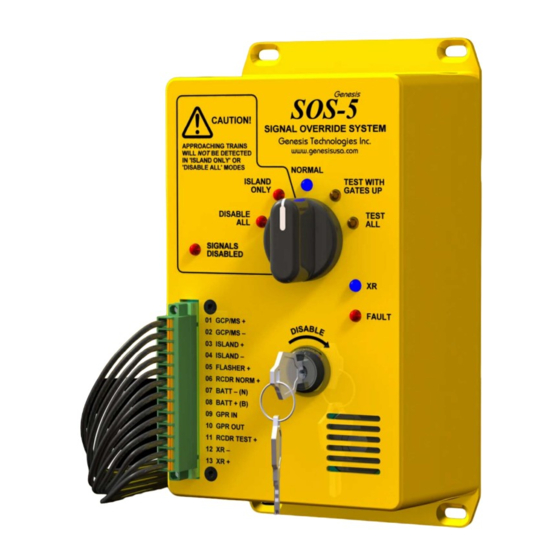
Five modes of operation:
1. DISABLE ALL – Disable All Signal Operation
2. ISLAND ONLY – Disable All Signal Operation Except Island
3. NORMAL – Normal Signal Operation
4. TEST WITH GATES UP – Signals Flashing with Gates Raised
5. TEST ALL – Signals Flashing with Gates Lowered
Multi-break Force-Guided Switch Contacts Route Inputs to (XR
Relay Output)
Flasher Output for Driving LED or Incandescent Warning
Indicator has 8 User Programmable Flash Patterns
Audio Annunciator Sounds when Signals are Disabled
Two Sequential and Separate Switch Position Settings
Required to Disable Signals
Recorder Outputs for NORMAL and TEST Modes
Plug-in Connector for Wiring Inputs and Outputs
Three-year Limited Warranty
Why Use a Signal Override System?
I
C
S
MPROVED
ROSSING
AFETY FOR THE
Most rail/highway signal malfunctions are "False Activations" with lights flashing and gates lowered and no trains approaching or
occupying the crossing. This usually results in disrupted highway traffic and calls from citizens and local law enforcement agencies
notifying the railroad of the problem.
When the railroad's signal maintainer is not readily available, a method is needed for railroad personnel not trained in signal maintenance
to safely disable the crossing signals until the maintainer can arrive to make necessary repairs or corrections.
The SOS-5 Signal Override System provides a simple and easy way to safely disable crossing signals in 3 simple steps:
1. DANGER!! Issue a crossing protection order before disabling signal operation according to your railroad's rules/instructions.
2. Rotate the selector switch to the ISLAND ONLY position then momentarily turn the keyswitch clockwise and release. If the malfunc-
tioning signals recover (turn OFF) then leave the switch in the ISLAND ONLY position/mode.
3. If step 2 (above) does not cause the signals to recover, then select the DISABLE ALL position/mode and again momentarily turn the
keyswitch clockwise and release. This should result in all signal operation being disabled, the Audible Annunciator sounding and
the flasher warning indicator (if installed) continuously flashing or on.
I
C
MPROVED
ONVENIENCE FOR THE
Each 30-day signal inspection requires that every flashing lamp unit be visually inspected for proper operation and visibility. This
inspection may take several minutes as it requires the maintainer to move across the tracks to view flashing lamps facing the opposite
direction. Of course during this time the gates are lowered and highway traffic is stopped.
To avoid delaying highway traffic during testing, the SOS-5 Signal Override System allows the signal maintainer to first activate the
flashers and lower the gates by placing the selector switch to the TEST ALL position. Once verification of proper gate operation has
been made, the maintainer can then move the selector switch to the TEST WITH GATES UP position which will leave the flashers on but
raise the gates. The maintainer can then proceed to visually inspect all flashing lamp units. For safety reasons the SOS-5 Signal
Override System will allow the gates to lower if an approaching train is detected by the train detection system.
Revised 20191118 - 16059PUB900
SOS-5
s i g n a l
R
P
AILROAD AND THE
UBLIC
R
S
M
AILROAD
IGNAL
AINTAINER AND THE
•
Genesis Technologies, Inc.
Tulsa, OK 74134
Genesis
o v e r r i d e
s y s t e m
B E N E F I T S
Malfunctioning crossing signal can be disabled safely and
easily by untrained railroad personnel
ISLAND ONLY operation provides protection while train is in
crossing (if island train detection is functioning properly)
TEST WITH GATES UP mode allows highway traffic movement
through crossing while signal maintainer visually inspects
flashing lamp units
Critical inputs utilize multi-break force-guided switch contacts
and supervisory circuits for determining the vital output to the
XR relay or crossing control unit.
Safeguard to prevent unintentional disabling of signals requires
two separate in-sequence switch position settings to disable
signals
Keyswitch can prevent unauthorized disabling of signals
Built-in warning flasher can power exterior indicator used for
warning train crews that crossing signal is disabled
Plug-in connector wiring requires no soldering, lugs or tools
M
P
OTORING
UBLIC
•
•
(918) 888-478-1299
www.genesisusa.com
Advertisement
Table of Contents

Subscribe to Our Youtube Channel
Related Manuals for Genesis SOS-5


Summary of Contents for Genesis SOS-5
- Page 1 TEST WITH GATES UP position which will leave the flashers on but raise the gates. The maintainer can then proceed to visually inspect all flashing lamp units. For safety reasons the SOS-5 Signal Override System will allow the gates to lower if an approaching train is detected by the train detection system.
- Page 2 The connector will accommodate one wire only for each connector position. DO NOT wire the plug-in connector with power applied or with it plugged in to the SOS-5 Signal Override System. An error in wiring or an inadvertent short to an adjacent pin may damage the SOS-5 or other connected equipment.
Need help?
Do you have a question about the SOS-5 and is the answer not in the manual?
Questions and answers