
Subscribe to Our Youtube Channel
Related Manuals for Makerfarm Prusa i3

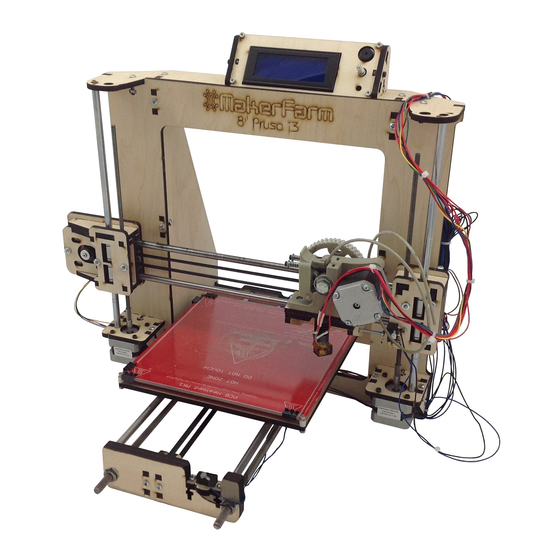
Summary of Contents for Makerfarm Prusa i3
- Page 2 You may also want some filament to print with after you have built your printer. Makerfarm.com does sell filament and if you purchase it with your kit you will receive a discount. If you want to purchase your filament somewhere else make sure you get high quality filament, poor quality filament (Amazon and eBay) will jam and cause problems.
- Page 3 X Carriage Gather the following parts before watching the X Carriage Video 5 x #6 Nuts 3 x #6 Lock Nuts (these will be installed on the 3 1” bolts) 2 x #6 .75” Bolts 3 x #6 1” Bolts 4 x #6 1.25”...
- Page 4 X Idler Gather the following parts before watching the X Idler Video 4 x #6 Lock Nuts (these will be installed on the 4 1.5” bolts) 4 x #6 1.5” Bolts 1 x #6 1.25” Bolt 2 x M5 washers 2 x M5 Nuts 1 x 625 Bearing 1 x M5x25mm Bolt...
- Page 5 X Motor Gather the following parts before watching the X Motor Video 3 x #6 Lock Nuts 2 x #6 1.5” Bolts 1 x #6 1” Bolt 4 x M3x10mm Bolts 1 x M5 Nut 2 x LM8UU Linear Bearings 1 x GT2 Pulley 1 x Motor X Motor Video...
-
Page 6: Axis Assembly
X Axis Assembly Gather the following parts before watching the X Axis Video 1 x Assembled X Carriage 1 x Assembled X Idler 1 x Assembled X Motor 2 x 15.5” Smooth Rods 1 x X Belt cut to 32” Long, loop the ends and secure with a zip tie, the end result should be a belt 29 7/8”... - Page 7 Y Idler Gather the following parts before watching the Y Idler Video 1 x M5x25mm Bolt 2 x M5 Washers 1 x M5 Nut 1 x 625 Bearing 4 x #6 .75” Bolt 4 x #6 Nuts 1 x Micro Switch 1 x Zip Tie Y Idler Video...
-
Page 8: Lcd Interface
LCD Interface Gather the following parts before watching the LCD Interface Video 4 x M3x16mm Bolt 2 x M3x10mm Bolt 6 x M3 Nuts 2 x #6 .75” Bolt 2 x #6 Nuts Ramps LCD Interface LCD Interface Video... - Page 9 Frame Gather the following parts before watching the Frame Video 24 x #6 .75” Bolt 24 x #6 Nuts Frame Video...
- Page 10 Y Bed Gather the following parts before watching the Y Bed Video 9 x #6 1” Bolt 9 x #6 Lock Nuts 3 x LM8UU Bearings For newer kits your heat bed mount will look different and have narrow slots for the bearings, the lower Y bearing holders will also look different and one will be marked “Y Endstop”, this one will be mounted in the front right corner of the heat bed mount (in the picture above it will be under the top left bearing hole).
- Page 11 If your bolt heads hit the frame you can sand away a little wood until the bolt heads clear. Y Bed Video...
- Page 12 Y Rods Gather the following parts before watching the Y Rods Video 2 x 15.75” 5/16” Threaded Rods 2 x 14.75” Smooth Rods 3 x LM8UU Bearings 12 x 5/16” Nuts 12 x 5/16” Washers 1 x GT2 Pulley 1 x Motor 1 x Y Belt cut to 26.5 “...
- Page 13 Z Rods Gather the following parts before watching the Z Rods Video 2 x Zip Tie 1 x Micro Switch 1 x Heat Bed (See RAMPS Setup Video) 4 x M3 16mm Bolt 4 x Nylon Spacer 4 x M3 Nuts 1 x Assembled X Axis 2 x Z Motors 2 x Clear Tubing...
- Page 14 .40mm Magma Hot End Gather the following parts before watching the Hot End Video 1 x Magma Hot End Kit 1 x Magma Accessory Bag 2 x M3x10mm bolts Magma Hot End Video...
- Page 15 .35mm or .50mm J-Head Hot End Gather the following parts before watching the Hot End Video 1 x Hot End Kit Newer versions of the Jhead include a Ceramic Heater, Watch the Magma video on Page 14 to see how to install the Ceramic Heater. Hot End Video...
- Page 16 Extruder Gather the following parts before watching the Extruder Video 1 x Extruder Printed Parts 1 x Extruder Hardware Bag Extruder Video, Download Printed Parts...
- Page 17 RAMPS Setup Gather the all your electronic parts before watching the RAMPS Setup Video, this diagram is a reference only, the colors of your wires may be different. The Magma fan will be connected to the Power supply, Not D8 as the Magma requires a fan to run all the time.
- Page 18 Wiring your Power Supply to your RAMPS Your ATX Power supply should have one or two high current 2x2pin power connector with Black and Yellow wires. Cut the 2x2 connectors off (This will void your Power supply Warranty if you have one).
- Page 19 Strip some wire off of the wires you cut and install in the power connector as shown below. Notice that the wires are all doubled up. The connection closest to D10, D9 and D8 is the 11amp connection that requires more current then the 5amp connecor.
- Page 20 Some Power supplies require a load on the 5v rail to keep the power supply on, if your power supply shuts off after a while try following the instructions here: PUTTING A LOAD ON THE 5V RAIL: http:// brazenartifice.wordpress.com/2011/12/26/atx-power-supply-5v-load -resistor-for-better-12v-regulation/...
- Page 21 Final Hardware Setup Your RAMPS electronics for your i3 will come pre-loaded with the correct firmware for your printer, but if you choose to change the RAMPS Firmware Video firmware you can watch the Windows 7 & XP Driver & Firmware for i3 Prusa Windows 8 Driver How to install an Unsigned Driver in Win 8 MAC OS X driver...
- Page 22 If your heat bed moves to the back of the printer instead you can turn the power supply off, unplug your usb cable and flip the connector around 180 degrees for the Y motor. Once the Bed moves the correct direction you can adjust the Y endstop until the nozzle is on the back edge of the Glass.
- Page 23 You should now be able to move your printer in all directions, but your endstops will only be used when you click one of the home buttons so don‘t keep telling your printer to go past that point. Slic3r - Now that we have the printer moving and calibrated we can slice some 3d objects so they can be printed.
- Page 24 Using the LCD interface The LCD interface will have a Rotary Knob, if you turn the knob at the main screen you can change the feed rate or speed at which the printer prints. If you push the rotary knob you can enter menus and select options.
-
Page 25: Troubleshooting
Troubleshooting: My Prints are shifting during the printing process. Typically when you print shifts to one side it due to one of a few different things. Lose belts or belts that are to tight. Mechanical binding, if your print head hits something during a print it can shift, or if your rods need to be cleaned and oiled there may be to much friction and your print can shift (you should wipe down and re-oil your smooth rods at least once a month). - Page 26 I would recommend using Makerfarm, Ultimachine or Makerbot filament as they are all known good sources, you can measure your filament and make sure its 3mm, if its above 3mm it can cause issues and jams, cheap filament also usually has debris in the filament which will cause jams and other issues.
- Page 27 Troubleshooting: My ABS prints warp or come off the glass before finished printing. Warping is caused because the edges of your print cool faster then the center of the print which causes them to shrink. There are a few things that can be done to help minimize or prevent this warping.
- Page 28 Troubleshooting: My computer didn’t install the printer on a com port. If windows doesn’t setup you printer on a com port most likely the driver hasn’t been installed yet. For windows xp and windows 7 you will first want to download the "Windows 7 &...
- Page 29 Troubleshooting: at that point you will click “Browse my computer for driver software” point to the folder that contains the file called "Arduino MEGA 2560.inf, and click next. If you get this message just click “Install this driver software anyway”...
- Page 30 Troubleshooting: it should install the driver, now you can click close. After that it will show up under your ports in the device manager. If that doesnt work you may try to carefullly remove the Arduino Mega from the RAMPS (the Arduino Mega has the USB plug and is the back board)
- Page 31 Troubleshooting: My Y rods don’t match up with the frame: If your Y rods don’t match the frame you will need to flip the two pieces shown at the back of the photo around 180 degrees. My Prints look bad, like they are putting out to much plastic: This is a common issue with newer versions of slic3r, to fix this download Slic3r 0.9.9 and re- slice any stl files you would like to print.
- Page 32 Troubleshooting: My Magma is taking a long time to reach 225c to print ABS. The Magma requires a fan to run all the time, this can also cause problems getting your hot end up to correct temperature. Here are a few things that can help. Wrap your brass nozzle with a few layers of kapton tape to insulate the thermistor.
- Page 33 Troubleshooting: I keep needing to adjust my Z axis or Z endstop There are a few things that can get the z motors out of sync, most of them stem from moving the z axis to fast. First thing to check is your z speed in pronterface, make sure it's set to 30 (see page 21 of the i3 guide) Next make sure you don't try to move the z axis using the "move axis"...
- Page 34 Troubleshooting: My endstops aren’t working properly The first thing we need to do is make sure the endstops are wired correctly and plugged into the electronics in the correct place, see page 17 for the wiring diagram. NOTE: the Blue wires should all be connected to the S Row, the Black wires connected to the - Row and the + Row will not be connected to a wire.
Need help?
Do you have a question about the Prusa i3 and is the answer not in the manual?
Questions and answers