Table of Contents
Advertisement
Visit www.carrier.com
Installation, Start-Up, and Operating Instructions
NOTE: Read the entire instruction manual before starting the
installation.
This symbol → indicates a change since the last issue.
Index
SAFETY CONSIDERATIONS .....................................................1
PROCEDURE ...........................................................................2
INTRODUCTION.......................................................................2-4
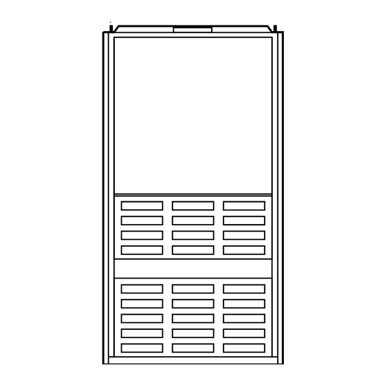
Dimensional Drawing ....................................................................2
Clearances to Combustibles......................................................3
LOCATION....................................................................................4
General ......................................................................................4
Location Relative to Cooling Equipment ................................4
Hazardous Locations.................................................................4
AIR FOR COMBUSTION AND VENTILATION...................4-5
Unconfined Space .....................................................................4
Confined Space......................................................................4-5
(DOWNFLOW) .....................................................................5-6
Installation On Combustible Floor...........................................6
HORIZONTAL ATTIC INSTALLATION...................................7
HORIZONTAL CRAWLSPACE INSTALLATION....................7
FILTER ARRANGEMENT...........................................................7
GAS PIPING...............................................................................7-9
ELECTRICAL CONNECTIONS ................................................10
115-v Wiring...........................................................................10
24-v Wiring.............................................................................10
Accessories..............................................................................10
VENTING ....................................................................................10
START-UP, ADJUSTMENT, AND SAFETY CHECK.......10-22
General...............................................................................10-12
Sequence of Operation ......................................................12-16
Adaptive Heating Mode ....................................................12-14
Non-Adaptive Heating Mode .................................................14
Cooling Mode ....................................................................14-15
Continuous Blower Mode.......................................................15
Heat Pump Mode ....................................................................15
Defrost Mode.....................................................................15-16
Start-Up Procedures ................................................................16
Adjustments .......................................................................16-22
Set Gas Input Rate ............................................................16-22
Set Temperature Rise ........................................................17-21
Set Thermostat Heat Anticipator ......................................21-22
Check Safety Controls ............................................................22
Checklist..................................................................................23
Manufacturer reserves the right to discontinue, or change at any time, specifications or designs without notice and without incurring obligations.
Book 1 4
PC 101
Catalog No. 535-887
Tab 6a 8a
Downflow/Horizontal 2-Speed, 2-Stage,
Induced-Combustion Gas Furnace
Sizes 065-125, Series 111
Page
Printed in U.S.A.
®
CERTIFICATION OF
MANUFACTURING SITE
SAFETY CONSIDERATIONS
Installing and servicing heating equipment can be hazardous due to
gas and electrical components. Only trained and qualified person-
nel should install, repair, or service heating equipment.
Untrained personnel can perform basic maintenance functions
such as cleaning and replacing air filters. All other operations must
be performed by trained service personnel. When working on
heating equipment, observe precautions in the literature, on tags,
and on labels attached to or shipped with the unit and other safety
precautions that may apply.
Follow all safety codes. In the United States, refer to the National
Fuel Gas Code (NFGC) NFPA No. 54-1996/ANSI Z223.1-1996.
In Canada, refer to the current edition of the National Standard of
Canada CAN/CGA-B149.1- and .2-M95 Natural Gas and Propane
Installation Codes (NSCNGPIC). Wear safety glasses and work
gloves. Have fire extinguisher available during start-up and
adjustment procedures and service calls.
Recognize safety information. This is the safety-alert symbol
When you see this symbol on the unit and in instructions or
manuals, be alert to the potential for personal injury.
Understand the signal words DANGER, WARNING, and CAU-
TION. These words are used with the safety-alert symbol. DAN-
GER identifies the most serious hazards which will result in severe
personal injury or death. WARNING signifies hazards which
could result in personal injury or death. CAUTION is used to
identify unsafe practices which would result in minor personal
injury or product and property damage.
These instructions cover minimum requirements and conform to
existing national standards and safety codes. In some instances,
these instructions exceed certain local codes and ordinances,
especially those that may not have kept up with changing residen-
tial construction practices. We require these instructions as a
minimum for a safe installation.
Form 58TMA-6SI
Pg 1
58TMA
ama
A PP R O VED
R
8-97
Replaces: 58TMA-4SI
.
Advertisement
Table of Contents

Related Manuals for Carrier DOWNFLOW HORIZONTAL 2-SPEED, 2-STAGE 58TMA


Summary of Contents for Carrier DOWNFLOW HORIZONTAL 2-SPEED, 2-STAGE 58TMA
-
Page 1: Table Of Contents
Downflow/Horizontal 2-Speed, 2-Stage, Visit www.carrier.com Installation, Start-Up, and Operating Instructions NOTE: Read the entire instruction manual before starting the installation. This symbol → indicates a change since the last issue. Index SAFETY CONSIDERATIONS ...1 ELECTROSTATIC DISCHARGE (ESD) PRECAUTIONS PROCEDURE ...2 INTRODUCTION...2-4... -
Page 2: Electrostatic Discharge (Esd) Precautions Procedure
These precautions will help to avoid exposing the control to electrostatic discharge by putting the furnace, the control, and the person at the same electrostatic potential. 1. Disconnect all power to the furnace. DO NOT TOUCH THE CONTROL OR ANY WIRE CONNECTED TO THE CON- TROL PRIOR TO DISCHARGING YOUR BODY’S ELEC-... -
Page 3: Clearances To Combustibles
This furnace is for indoor installation in a building constructed on site. This furnace may be installed on combustible flooring in alcove or closet at minimum clearance from combustible material. This furnace may be used with a Type B-1 Vent and may be vented in common with other gas-fired appliances. †... -
Page 4: Location
The furnace should be installed as level as possible. When furnace is installed so that supply ducts carry air to areas outside space containing furnace, the return air must also be handled by a duct(s) sealed to furnace casing and terminating outside space containing furnace. -
Page 5: Air For Combustion And Ventilation
See item 2 below. c. If furnace is installed on a raised platform to provide a return-air plenum, and return air is taken directly from hallway or space adjacent to furnace, all air for combustion must come from outdoors. -
Page 6: Installation On Combustible Floor
105,000 123,000 KGASB0201ALL is used. Manufacturer’s accessory floor base is not required when this furnace is installed on manufacturer’s Coil Assembly Part No. CD5 or CK5, or Coil Box Part No. KCAKC is used. 1. Determine application being installed from Table 3. -
Page 7: Horizontal Attic Installation
Do not install furnace on its back; safety control operation will be adversely affected. Never connect return-air ducts to the sides or back of the furnace. A failure to follow this warning could result in fire, personal injury, or death. - Page 8 LINE CONTACT ONLY PERMISSIBLE BETWEEN LINES FORMED BY INTERSECTIONS OF THE TOP AND TWO SIDES OF THE FURNACE JACKET AND BUILDING JOISTS, STUDS, OR FRAMING. MANUAL SHUTOFF GAS VALVE SEDIMENT TRAP Fig. 8—Typical Attic Installation ANGLE IRON OR EQUIVALENT ROD LOCATION...
- Page 9 Place ground joint union between gas control manifold and manual shutoff. Install sediment trap in riser leading to furnace. The trap can be installed by connecting a tee to riser leading from furnace. Connect capped nipple into lower end of tee. The capped nipple should extend below level of gas controls.
-
Page 10: Electrical Connections
CSA C22.1 Canadian Electrical Code or authori- ties having jurisdiction. NOTE: Proper polarity must be maintained for 115-v wiring. If polarity is incorrect, the furnace control status LED will flash rapidly and prevent heating operation. → The cabinet must have an uninterrupted or unbroken ground according to NEC ANSI/NFPA 70-1996 and Canadian Elec- trical Code CSA C22.1 or local codes to minimize personal... - Page 11 (WHEN REQUIRED) FURNACE → Fig. 15—Heating and Cooling Application Wiring Diagram With 1-Stage Thermostat and Condensing Unit This furnace can be installed with either single-stage heating or 2-stage heating thermostat. For single-stage thermostats, connect thermostat W to W/W1 at furnace control terminal block. (See Fig. 15.) For single-stage...
-
Page 12: Sequence Of Operation
MODE BLOWER OFF SW-3 DELAY (SEC) his furnace is equipped with 2 manual reset limit switches in gas control area. The switches will open and shut off power to gas valve if a flame rollout or an overheating condition occurs in gas control area. DO NOT bypass switches. Correct inadequate combustion air supply, component failure, re- stricted flue gas passageway before resetting switches. - Page 13 USED) (WHEN NOTE SETTINGS FACTORY...
-
Page 14: Non-Adaptive Heating Mode
The furnace starts up in either low- or high-gas heat. If furnace starts up in low-gas heat, control CPU determines low-gas heat on time (from 0 to 16 minutes) which is permitted before switching to high-gas heat. If power is interrupted, stored history is erased, and control... -
Page 15: Continuous Blower Mode
R to G-and-Y2 circuits start furnace blower motor BLWM on high-cooling speed. NOTE: Y1 is not located on furnace control, but is found in outdoor unit. The furnace control CPU controls blower motor BLWM speed by sensing only G for low-cooling speed and Y/Y2 for high-cooling speed. -
Page 16: Start-Up Procedures
Obtain yearly specific gravity average from local gas supplier. c. Verify furnace model. Table 10 can only be used for model 58TMA Furnaces. d. Find installation altitude in Table 10. NOTE: For Canada altitudes of 2000 to 4500 ft, use U.S.A. -
Page 17: Set Temperature Rise
±2 percent of the furnace input rate. NOTE: Measured gas inputs (high heat and low heat) must be within ±2 percent of that stated on furnace rating plate when installed at sea level or derated per that stated above when installed at higher altitudes. - Page 18 Table 10—Model 58TMA Orifice Size and Manifold Pressure for Correct Input (Tabulated Data Based on 21,000 Btuh High Heat/13,500 Btuh Low Heat per Burner, Derated 4% for Each 1000 Ft Above Sea Level)* AVG GAS ALTITUDE HEAT VALUE RANGE AT ALTITUDE Orifice (FT) (BTU/CU FT)
- Page 19 Table 10—Model 58TMA Orifice Size and Manifold Pressure for Correct Input—Continued (TABULATED DATA BASED ON 21,000 BTUH HIGH HEAT/13,500 BTUH LOW HEAT PER BURNER, DERATED 4% FOR EACH 1000 FT ABOVE SEA LEVEL)* AVG GAS ALTITUDE HEAT VALUE RANGE AT ALTITUDE Orifice (FT) (BTU/CU FT)
- Page 20 Table 10—Model 58TMA Orifice Size and Manifold Pressure for Correct Input—Continued (TABULATED DATA BASED ON 21,000 BTUH HIGH HEAT/13,500 BTUH LOW HEAT PER BURNER, DERATED 4% FOR EACH 1000 FT ABOVE SEA LEVEL)* AVG GAS ALTITUDE HEAT VALUE RANGE AT ALTITUDE Orifice (FT) (BTU/CU FT)
-
Page 21: Set Thermostat Heat Anticipator
1059 1000 a. Place duct thermometers in return and supply ducts as near furnace as possible. Be sure thermometers do not see heat exchangers so that radiant heat will not affect thermometer readings. This is particularly important with straight-run ducts. -
Page 22: Check Safety Controls
The amp reading should be taken after blower motor has started and furnace is operating in low heat. To operate furnace in low heat, first move SW-2 to ON position, THEN connect ammeter wires as shown in Fig. -
Page 23: Checklist
3. Verify manual reset switches have continuity. 4. Ensure blower and gas control access doors are properly installed. 5. Cycle test furnace with room thermostat. 6. Check operation of accessories per manufacturer’s instruc- tions. 7. Review User’s Manual with owner. -
Page 24: Service Training
[ ] Packaged Service Training [ ] Classroom Service Training Copyright 1997 CARRIER Corp. • 7310 W. Morris St. • Indianapolis, IN 46231 Manufacturer reserves the right to discontinue, or change at any time, specifications or designs without notice and without incurring obligations.
Need help?
Do you have a question about the DOWNFLOW HORIZONTAL 2-SPEED, 2-STAGE 58TMA and is the answer not in the manual?
Questions and answers