Table of Contents
Advertisement
Quick Links
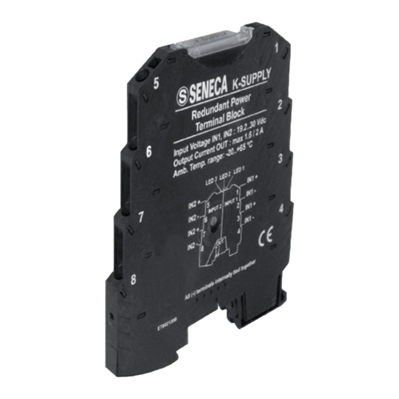
K-SUPPLY
EN
K-BUS power supply for K-Series modules
General Description
The K-SUPPLY module permits the delivery of power supply to numerous K-Series
modules through K-BUS connection by creating interface between an external power
supply system and the user module distribution bus. The impossibility of tapping
current from the bus to the input terminals permits the connection of numerous K-
SUPPLY modules in parallel on the same bus together with the protection provided
against polarity inversion permits the module to offer valid protection against
erroneous connections.
Main features:
two independent inputs that permit the use of one power supply system; redundant
power supply that guarantees the presence of power supply even whenever the
source of either input undergoes power failure;
indication of the presence of each channel: the LED switches on only when there is
sufficient voltage for the operation of the K-Series modules connected;
a LED that signals input inverted polarity or alternating current;
built-in over-voltage (surge) protection;
differential mode filter.
Technical features
Input characteristics
Number:
Type:
Voltage:
Current carrying capacity:
Protection:
2, with shared negative terminal.
Pass-through: each input can be accessed by two
pairs of terminals, in this way permitting the same
power supply source to be used for more than one
K-Supply module (see the section entitled Example
of Connection to more than one bus).
19,2..30 Vdc
Maximum current per terminal: 4 A
Each positive input must be provided with protection
by an external fuse (see the section entitled Fuse
Sizing Selection).
The device has no limit on maximum current.
MI000951-E
ENGLISH - 1/8
Advertisement
Table of Contents

Related Manuals for Seneca K-SUPPLY


Summary of Contents for Seneca K-SUPPLY
- Page 1 K-BUS power supply for K-Series modules General Description The K-SUPPLY module permits the delivery of power supply to numerous K-Series modules through K-BUS connection by creating interface between an external power supply system and the user module distribution bus. The impossibility of tapping...
- Page 2 Output characteristics 300 mV Maximum voltage drop: Input voltage minus internal voltage drooping value. Voltage : One single input: maximum 1.6 A Current carrying capacity: Inputs 1 and 2 connected in parallel: maximum 2 A . Other electrical characteristics Filter: Differential mode, equal to 4.7 mH &...
- Page 3 Installation rules This module has been designed for assembly on a DIN 46277 rail. Assembly in vertical position is recommended in order to increase the module's ventilation, and no raceways or other objects that compromise aeration must be positioned in the vicinity. Do not position the module above equipment that generates heat;...
- Page 4 Fuse sizing selection This section provides indications on the sizing of the fuse to be used for the protection of the inputs as required by the number of boards that the K-SUPPLY module must power. The table below provides the sizing recommended per type of fuse for battery-powered systems (21…30 V) in which surge is not foreseen.
- Page 5 Electrical connections Internal wiring diagram IN2 + IN2 - IN1 - IN2 + IN1 + IN2 - IN1 - 0,2..2,5 mm 8 mm Inputs The module has two inputs (19.2…30V DC) with shared negative terminal. Input 1 Terminal 1 & Terminal 3: + Terminal 2 &...
- Page 6 Example of connection with REDUNDANT POWER SUPPLY Main Main INPUT 2 INPUT 1 Power-supply 2 Power-supply 1 Bus for supplying K serie devices Example of connection to more than one bus Main Power-supply INPUT 2 INPUT 1 INPUT 1 INPUT 2 Bus 2 Bus 1 Example of connection with inputs connected in parallel: 2 A output...
- Page 7 Signalling by LED on the front panel Meaning Green Led 1 When illuminated, this LED signals the presence of sufficient voltage for the first input. The illumination threshold is 19.2 V ± 0.3 V Green Led 2 When illuminated, this LED signals the presence of sufficient voltage for a second input.
- Page 8 This document is property of SENECA srl. Duplication and reprodution are forbidden, if not authorized. Contents of the present documentation refers to products and technologies described in it. All technical data contained in the document may be modified without prior notice Content of this documentation is subject to periodical revision.
Need help?
Do you have a question about the K-SUPPLY and is the answer not in the manual?
Questions and answers