Table of Contents
Advertisement
Quick Links
Advertisement
Table of Contents

Subscribe to Our Youtube Channel
Related Manuals for KaVo KaVoLUX 540 LED U


Summary of Contents for KaVo KaVoLUX 540 LED U
- Page 1 Technician's instructions KaVoLUX 540 LED U / T...
- Page 2 Distributed by: Manufacturer: KaVo Dental GmbH Kaltenbach & Voigt GmbH Bismarckring 39 Bismarckring 39 D-88400 Biberach D-88400 Biberach Phone +49 (0) 7351 56-0 www.kavo.com Fax +49 (0) 7351 56-1488...
-
Page 3: Table Of Contents
6.3 Set the brakes on the operating light head .................... 26 6.3.1 Setting the rotary motion und 3D joint movement..............26 6.3.2 Adjusting the light head brake....................27 7 Firmware update............................. 29 7.1 Firmware update KaVoLUX 540 LED U to E50 ..................29 3 / 56... - Page 4 Technician's instructions KaVoLUX 540 LED U / T Table of contents 7.2 Firmware update KaVoLUX 540 LED U to E70/E80 and KaVoLUX 540 LED T........30 8 Service mode KaVoLUX 540 LED........................33 8.1 Service mode KaVoLUX 540 LED U (unit) .................... 33 8.2 Service mode KaVoLUX 540 LED T (Touchpad) ..................
-
Page 5: User Instructions
Technician's instructions KaVoLUX 540 LED U / T 1 User instructions | 1.1 User guide 1 User instructions 1.1 User guide Requirement Read these instructions before the initial startup to prevent misuse and damage. 1.1.1 Abbreviations Abbre- Explanation viation Instructions for use... -
Page 6: Terms And Conditions Of Warranty
Claims from this warranty can only be asserted when the transfer form (copy) belong- ing to the product has been sent to KaVo, and the original can be presented by the op- erator or user. -
Page 7: Information On The Packaging: Storage And Transportation
Art. 28). Outside Germany Note KaVo shall not be held liable for damage arising from transportation. The shipment must be checked on arrival. If the packaging is visibly damaged on delivery, please proceed as follows: 1. The recipient of the package must record the loss or damage on the delivery re- ceipt. - Page 8 Technician's instructions KaVoLUX 540 LED U / T 1 User instructions | 1.4 Transportation and storage Permissible stacking load Temperature range Humidity Air pressure 8 / 56...
-
Page 9: Safety
2.2 Purpose – Proper use The dental operating lights KaVoLUX 540 LED U and T are designed for the illumina- tion of the oral cavity of a patient during the dental treatment. The lights are mounted to the dental treatment units, the use is restricted to medical specialist staff in rooms used for medical purposes. -
Page 10: Information On Electromagnetic Compatibility
Application of and compliance with the general guidelines and/or national laws, na- tional regulations, and the rules of technology applicable to this product for start-up and use of the KaVo product for the intended purpose are to be applied and complied with. -
Page 11: Disposal
Technician's instructions KaVoLUX 540 LED U / T 2 Safety | 2.2 Purpose – Proper use Note KaVo cannot guarantee the compliance of accessories, cables, and other compon- ents not supplied by KaVo with the EMC requirements of IEC 60601-1-2 (DIN EN 60601-1-2). 2.2.2 Disposal Note... -
Page 12: Safety Instructions
▶ When using the KaVo KEY Laser III or the KEY Laser 3+, switch the operating light to laser mode. ▶ Or switch off the operating light, do not use the KaVo KEY Laser III or KEY Laser 3+ and the KaVoLUX 540 LED operating light simultaneously. - Page 13 Technician's instructions KaVoLUX 540 LED U / T 2 Safety | 2.3 Safety instructions CAUTION Electrostatic discharge. Destroys electronic components. ▶ Before you touch the electronic circuit boards, always earth them by touching the earthing conductor (PE). ▶ When working on an open unit, takes precautions against ESD.
-
Page 14: Function Description
See also: 2 GA treatment centre Chapter Operation Note For operation with the KaVoLUX 540 LED U, the treatment centre must be compat- ible and the operating light type (KaVoLUX 540) must be set in service mode. 14 / 56... -
Page 15: Operating Light Kavolux 540 Led T (Touchpad)
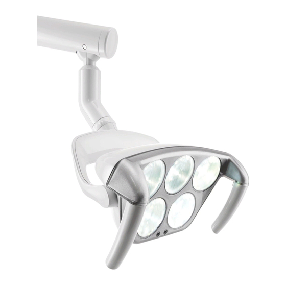
① Top lighting unit 3 units ② Bottom lighting unit 2 units The operating light KaVoLUX 540 LED U / T is equipped with five lighting units in the light head. These are supplied with voltage via the PCBA control operating light, ac- cording to the setting. -
Page 16: Dimensions And Swing Range
Technician's instructions KaVoLUX 540 LED U / T 3 Function description | 3.4 Dimensions and swing range Presentation of treatment unit Each lighting unit possesses four LEDs in different colours, which in the case of cer- tain activation, mix and transmit different colour temperatures. - Page 17 Technician's instructions KaVoLUX 540 LED U / T 3 Function description | 3.4 Dimensions and swing range Dimensions (in mm) Swing ranges (in mm) 17 / 56...
-
Page 18: Technical Data And Requirements
Technician's instructions KaVoLUX 540 LED U / T 3 Function description | 3.5 Technical data and requirements 3.5 Technical data and requirements Input voltage 24 V AC Frequency 50/60 Hertz Power consumption max. 35 VA Colour temperature normal light ca 4.000 to 6.000 Kelvin; preset 5.500... -
Page 19: Electrical Controls
Technician's instructions KaVoLUX 540 LED U / T 4 Electrical controls | 4.1 Description of circuit board 4 Electrical controls 4.1 Description of circuit board Mat. no. 10084486 Features of PCBA control operating lights: ▪ The PCBA control operating light receives its input voltage 24 V AC from the treat- ment centre or from the ceiling mounting kit ▪... - Page 20 Technician's instructions KaVoLUX 540 LED U / T 4 Electrical controls | 4.1 Description of circuit board Plug Plug Description Supply voltage KaVoLUX 540 LED T / U CAN connection only with KaVoLUX 540 LED U Slot for programming adapter...
-
Page 21: Wiring Diagram
Technician's instructions KaVoLUX 540 LED U / T 4 Electrical controls | 4.2 Wiring diagram 4.2 Wiring diagram 4.2.1 KaVoLUX 540 LED U / T 21 / 56... -
Page 22: Ceiling Mounting Set
Technician's instructions KaVoLUX 540 LED U / T 4 Electrical controls | 4.2 Wiring diagram 4.2.2 Ceiling mounting set 22 / 56... -
Page 23: Assembling And Disassembling The Cladding
Technician's instructions KaVoLUX 540 LED U / T 5 Assembling and disassembling the cladding | 4.2 Wiring diagram 5 Assembling and disassembling the cladding CAUTION Dirt or finger prints on the illumination units affect(s) the reflection on the optical ele- ments. -
Page 24: Disassembly Of The Glass Cover
Technician's instructions KaVoLUX 540 LED U / T 5 Assembling and disassembling the cladding | 5.1 Disassembly of the glass cover See also: 2 5.1 Disassembly of the glass cover, Page 24 5.1 Disassembly of the glass cover CAUTION The operating light may be hot. -
Page 25: Mechanical Settings
Technician's instructions KaVoLUX 540 LED U / T 6 Mechanical settings | 6.1 Adjusting the swinging arm brake 6 Mechanical settings 6.1 Adjusting the swinging arm brake Note The swinging arm brake determines the ease with which the swinging arm rotates. -
Page 26: Set The Brakes On The Operating Light Head
Technician's instructions KaVoLUX 540 LED U / T 6 Mechanical settings | 6.3 Set the brakes on the operating light head 6.3 Set the brakes on the operating light head Note All movements of the light head can be set using different brakes. -
Page 27: Adjusting The Light Head Brake
Technician's instructions KaVoLUX 540 LED U / T 6 Mechanical settings | 6.3 Set the brakes on the operating light head ▶ Take off cover ⑤. ▶ Use the adjusting screw ④ to set the smooth running of the rotary motion. - Page 28 Technician's instructions KaVoLUX 540 LED U / T 6 Mechanical settings | 6.3 Set the brakes on the operating light head Fine adjustment ▶ Pivot the light head upwards until the orifice in the cover of the cross slot adjust- ment screw ①...
-
Page 29: Firmware Update
A firmware update can be carried out via the Media Gateway and an SD Card. The function of the KaVoLUX 540 LED is integrated from the E50 firmware version 1.5.2. You can find and download the current firmware for the E50 in the "KaVo ex- tranet" under http://extranet.kavo.com. -
Page 30: Firmware Update Kavolux 540 Led U To E70/E80 And Kavolux 540 Led T
Technician's instructions KaVoLUX 540 LED U / T 7 Firmware update | 7.2 Firmware update KaVoLUX 540 LED U to E70/E80 and KaVoLUX 540 LED T ▶ Invoke option 14 in the user menu to verify the firmware version of the E50. - Page 31 Technician's instructions KaVoLUX 540 LED U / T 7 Firmware update | 7.2 Firmware update KaVoLUX 540 LED U to E70/E80 and KaVoLUX 540 LED T ▶ Switch off the supply voltage for the operating light. ▶ Remove the glass cover.
- Page 32 Technician's instructions KaVoLUX 540 LED U / T 7 Firmware update | 7.2 Firmware update KaVoLUX 540 LED U to E70/E80 and KaVoLUX 540 LED T ▶ Remount the glass cover and the handles. 32 / 56...
-
Page 33: Service Mode Kavolux 540 Led
Technician's instructions KaVoLUX 540 LED U / T 8 Service mode KaVoLUX 540 LED | 8.1 Service mode KaVoLUX 540 LED U (unit) 8 Service mode KaVoLUX 540 LED 8.1 Service mode KaVoLUX 540 LED U (unit) Note With the KaVoLUX 540 LED U the firmware version of the LED operating light can be displayed in the service mode of the relevant treatment centre. - Page 34 Technician's instructions KaVoLUX 540 LED U / T 8 Service mode KaVoLUX 540 LED | 8.2 Service mode KaVoLUX 540 LED T (Touchpad) Example: Display of firmware version 1.3.2 Service mode Display 1. ver- Display 2. ver- Display 3. ver-...
-
Page 35: Cleaning And Disinfection Of The Light And Glass Cover
Technician's instructions KaVoLUX 540 LED U / T 9 Cleaning and disinfection of the light and glass cover | 9.1 External cleaning 9 Cleaning and disinfection of the light and glass cover 9.1 External cleaning Note Clean the light and glass cover only after the light has been switched off and cooled down. -
Page 36: Sterilisation
Technician's instructions KaVoLUX 540 LED U / T 9 Cleaning and disinfection of the light and glass cover | 9.3 Sterilisation CAUTION Scratching of the glass cover during assembly/ disassembly. Product damage. ▶ Mount or dismount the glass cover carefully. -
Page 37: Troubleshooting
Technician's instructions KaVoLUX 540 LED U / T 10 Troubleshooting | 9.3 Sterilisation 10 Troubleshooting Note If disturbance arises, a technician authorised by KaVo must be engaged for the re- medial action. Malfunction Cause Remedy ▶ Maintain an ambient temperature of max. 40 °C. -
Page 38: Replace The Gas Spring
Technician's instructions KaVoLUX 540 LED U / T 10 Troubleshooting | 10.1 Replace the gas spring. Malfunction Cause Remedy ▶ Replace the strip line. A colour circle (white, yel- Strip line is defective. low, cyan, red) has com- ▶ Replace the luminaire insert. -
Page 39: Install The Luminaire Insert From The Operating Light Head
Technician's instructions KaVoLUX 540 LED U / T 10 Troubleshooting | 10.2 Install the luminaire insert from the operating light head ▶ Screw on the plate ④. ▶ Screw in the pin grub screw M10 ③; this tensions the gas spring. -
Page 40: Repair The Luminaire Insert
Technician's instructions KaVoLUX 540 LED U / T 10 Troubleshooting | 10.3 Repair the luminaire insert ▶ Pull out the strip line from the proximity sensor ①. ▶ Remove 7 x cheese head screws ④. ▶ Pull out cable X1 and, for the T version, plug X5 from the PCBA control operating light ②. - Page 41 Technician's instructions KaVoLUX 540 LED U / T 10 Troubleshooting | 10.3 Repair the luminaire insert CAUTION Cable break due to bending the strip line. Product damage. ▶ Do not bend the strip line during insertion. ▶ Lay the luminaire insert with the installed strip line on a soft surface on the lighting units.
-
Page 42: Safety Checks - Test Instructions
11.1 Mounting the device Note The test instructions for the KaVoLUX 540 LED U / T to be mounted to devices are described in the instructions for use of the respective treatment unit The measurement of the protective earth, defined in the instructions for use for the relevant treatment unit, must be extended to include the measuring points "Scan... - Page 43 Note If the unit comprises several electrical devices or electrical devices from several manufacturers that are connected to a system in connection with the KaVo dental unit, the manufacturer data contained in the instructions for use for all products sub- ject to safety controls must also be observed.
- Page 44 Technician's instructions KaVoLUX 540 LED U / T 11 Safety checks - Test instructions | 11.2 Ceiling mounting Note An ME system that is connected to the power supply mains by means of a multiple socket outlet must be treated as one device during checks and testing.
-
Page 45: Safety Check Instructions
Technician's instructions KaVoLUX 540 LED U / T 11 Safety checks - Test instructions | 11.2 Ceiling mounting ▪ Type B ▪ The device is firmly connected / threshold: SL < 0,3 Ω ▪ Measurement according to EUL / threshold limit: < 10 mA* *The EUL threshold is compatible with the value defined in IEC 60601 (DIN EN 60601), taking comment 2 from table 2 into consideration. - Page 46 Technician's instructions KaVoLUX 540 LED U / T 11 Safety checks - Test instructions | 11.2 Ceiling mounting Mounting location: rating plate Check of availability of required documents ▶ Verify whether the required instructions for use and care instructions are available in the surgery.
- Page 47 L & N on the power input board need not be disconnected. The adapter cable ② is included in the delivery of the KaVo measuring cable and is re- quired for older treatment centres that are not equipped with an X2 connector.
- Page 48 Technician's instructions KaVoLUX 540 LED U / T 11 Safety checks - Test instructions | 11.2 Ceiling mounting Connecting the safety tester to the treatment centre without a KaVo measuring cable ▶ Switch L + N of the on-site power supply cord to be voltage-free.
- Page 49 Technician's instructions KaVoLUX 540 LED U / T 11 Safety checks - Test instructions | 11.2 Ceiling mounting Note The integrity of the power supply cable, in particular the protective earth wire of the power cable must be ensured. As this is a fixed installation, the evaulation can be conducted by means of a visual inspection.
- Page 50 Technician's instructions KaVoLUX 540 LED U / T 11 Safety checks - Test instructions | 11.2 Ceiling mounting Scan the ceiling adapter of the treatment light with the probe ① Base plate for the ceiling adapter ② Surroundings of the protective con- ductor connector ③...
- Page 51 Technician's instructions KaVoLUX 540 LED U / T 11 Safety checks - Test instructions | 11.2 Ceiling mounting Scan the light head of the treatment light KaVoLUX 540 LED with the probe ① Fastening screw of the handle support when the gripping sleeve has been re-...
- Page 52 ▶ Final evaluation ▶ Name, date and signature of test engineer There is a copy of a test report template at the end of chapter STK. KaVo recom- mends the use of this template. Note Following testing, repair or adjustment, it must be verified whether the ME equip- ment or ME system has been restored to the state that is required for the intended usage before it is employed once again.
-
Page 53: Safety Check [Stk] Test Protocol
Technician's instructions KaVoLUX 540 LED U / T 11 Safety checks - Test instructions | 11.2 Ceiling mounting 11.2.3 Safety Check [STK] Test Protocol 53 / 56...
Need help?
Do you have a question about the KaVoLUX 540 LED U and is the answer not in the manual?
Questions and answers