Dini Argeo LTP Installation And Operating Instructions Manual
Forklift hydraulic weighing system
Hide thumbs
Also See for LTP:
- Installation and operating instructions manual (40 pages) ,
- Operating instructions manual (32 pages) ,
- Operating instructions manual (28 pages)

Related Manuals for Dini Argeo LTP


Summary of Contents for Dini Argeo LTP
- Page 1 Forklift hydraulic weighing system INSTALLATION AND OPERATING INSTRUCTIONS ENGLISH www.diniargeo.com...
-
Page 3: Table Of Contents
Contents Introduction Weighing system specifications Warnings Forklift requirements Kit components 6 Weight indicator 8 Pressure sensor 8 Fixing bracket for the indicator in the cabin 8 Reference stickers Kit installation 10 Before installation 11 Sensor installation ... -
Page 4: Introduction
Introduction Dear Customer, Thank you for purchasing a DINI ARGEO product. This manual explains the installation and commissioning for the hydraulic weighing system for forklifts. In particular, the installation of the sensor and the calibration of the indicator are described (with the corresponding adjustable ranges of values and practical programming examples) to assist the technician during system installation. -
Page 5: Warnings
• Please read this manual carefully before using the system. • Assistance must only be carried out by personnel authorised by Dini Argeo. • Dini Argeo is not responsible for any weighing errors resulting from improper use of the system. Forklift requirements For proper operation of the system, the forklift must meet the following requirements: •... -
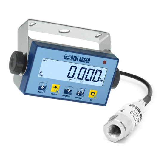
Page 6: Kit Components
Kit components The LTP kit consists of: • Weight indicator • Pressure sensor • Fixing bracket to the forklift • Reference stickers • Power supply unit (optional) • Thermal printer (optional) 1. Weight indicator Powered directly from the forklift battery (via optional internal power supply), 5-key keypad and LCD Vertical tilt can be adjusted via the integrated bracket. - Page 7 DISPLAY AND KEYBOARD ITEM ICON DESCRIPTION This indicates that the scale is empty (gross zero). This indicates that the weight is unstable. The net weight is displayed. Note: A tare has been stored. 4 / 5 The gross weight is displayed. This indicates the battery level: A tare has been blocked.
-
Page 8: Fixing Bracket For The Indicator In The Cabin
2. Pressure sensor Stainless steel sensor, IP65 protection rating and hydraulic connector with 1/4 inch parallel PSB female. Sensor dimensions: length: 73.5 mm; diameter: 24.5 mm. 3. Fixing bracket for the indicator in the cabin Bracket for horizontal adjustment during installation. 4. - Page 9 5. Power supply unit (optional) The appropriate optional ALxxV5 power supply unit with 18 to 72Vdc or 40 to 160Vdc input can be chosen according to the voltage on the forklift. The ALxxV5 power supply units can be installed inside the weight indicator and can simultaneously power the OBTPRLT printer, optimising the wiring of the various components.
-
Page 10: Kit Installation
Kit installation Before installation • Check that the maximum oil pressure is lower than the maximum value indicated on the sensor datasheet (4000 psi = 280 bar). • Remove the pressure in the hydraulic circuit; this can be done in two ways: Lower the forks to their maximum Place the forks on a stable object. -
Page 11: Sensor Installation
Sensor installation The sensor is connected to the hydraulic system of the forklift using a compatible tee fitting (not included in the kit). Install the sensor in the pressure pipe that guides the cylinder (the sensor should be positioned as close as possible to the cylinder). The sensor must be installed with the cable pointing downwards. -
Page 12: Installing The Indicator
Installing the indicator FIND A SUITABLE LOCATION FOR THE INDICATOR: Below are some installation examples: Adjust the orientation of the indicator vertically and horizontally so that it is clearly visible and easy to reach. INSTALLING THE INDICATOR BRACKET Install the bracket to the indicator using the supplied fixing components. The power cable and the sensor cable are then connected via the two side cable glands. - Page 13 SHIELD YELLOW SEN+ EXC+ SEN- EXC- INDICATOR POWER SUPPLY 5 Vdc from forklift through power supply (Dini Argeo supplies two power supply units that can be installed inside the indicator, optional). 12Vdc POWER RS232 COM 2 RS232 COM 1 BATTERY...
-
Page 14: Applying Reference Stickers
Applying reference stickers Apply the stickers at a height of at least 50 cm from the ground. Apply the arrow-shaped sticker to the forklift plate and the rectangular sticker to the upright. These stickers identify the reference area: perform all weighing operations when the arrowhead is inside the yellow band. The operator must have full visibility of the reference stickers. -
Page 15: Calibration
Calibration FOREWORD The system detects the weight based on the pressure trend as a function of time. As each forklift has a different behaviour, it is recommended to use the LTPTOOL PC software to optimise the response speed and accuracy of the weighing system according to the conditions and characteristics of the forklift. - Page 16 4 OPTIMISING TIMES WITH LTPTOOL Select the “Settings” tab and select the serial port. Click on “Connect”. Set the number of up / down cycles (default = 5). By increasing the number of cycles, the procedure becomes longer but the results will be more reliable.
- Page 17 Click on “Start” and follow the instructions in the box in the bottom left. The times to be used during calibration are shown at the end of the acquisition. TECH_MAN_ENG_LTP...
- Page 18 P2 = tim.avG s 2.0 Place a pallet on the forks How to set the value TIM.AVG Set the values calculated by LTP Tool s 1.0 and press Repeat the lifting / lowering operations raise.f lower.f of the forks 3 times wait •••...
-
Page 19: Calibration Linearisation
Calibration linearisation Perform the linearisation after calibration to increase weighing accuracy. Linearising the calibration means adding calibration points (up to 6). The more calibration points that are added, the more accurate the system will be. We recommend defining at least 2 linearisation points. Example: On a system with a capacity of 2000 kg, assuming an initial calibration with 2000 kg, we recommend adding 3 calibration points at 500 kg, 1000 kg, 1500 kg. -
Page 20: Additional Parameters (For Experienced Users Only)
Additional parameters (for experienced users only) There are also a number of parameters to further configure the behaviour of the indicator. ConfiG CloCk 5 sec div.zmk din.WGT div.unf WGt,unf tim.up tim.avG DESCRIPTION OF THE PARAMETERS: div.zmk Number of divisions to mask around zero. If the displacement of the weight from zero does not exceed the number of divisions set in DIV.ZMK the indicator will continue to display 0. - Page 21 tim.up Waiting time between end of fork ascent and start of acquisition Used to delay the acquisition of the weighing. tim.avG Weight acquisition time. The weight is obtained by averaging the values acquired during the set time. Access to the menu can be locked using a password.
-
Page 22: Programming Menu
Programming menu Calibration..........................15 0.CAL Zeroring the pre-tare (zero calibration) ................23 Cal.adv Advanced calibration......................23 Serial Configuration of the serial ports ..................26 laYoUT Print customisation ..........................31 SCreen Adjusting the display ......................39 AutoFF Auto switch-off ............................40 sCr.sav Screen-saver ............................40 reset Factory configuration reset ....................40 diaG... -
Page 23: Cal.adv
MENU 0 . Cal Zeroring the pre-tare Enter Browse Save and exit Acquisition of the zero point 1. Off 0 . Cal sure? -ok- 2. On GRAV Page 15 Page 15 See the “Calibration” chapter Cal.adv Advanced calibration 0.CAL Cal.adV Cal.Par Calibration parameters CAL.PAR... - Page 24 MENU Unit of measure U . M . C-1-3 Enter Browse Save and exit 1. Off 2. On Page 15 Page 15 0.CAL Cal.adV CAL.PAR Serial CAPAC Metrol laYoUT DECIM Cal.ADj SCreen U.M. Cal.man autoff Scale capacity. Set Max or Range 1 (Max range = 800.000) RanGe 1 Scr.Sav 002500...
- Page 25 MENU Metrol Metrological parameters Enter Browse Save and exit Filter configuration 1. Off filter C-2-1 2. On stand.0 Page 15 Page 15 stand.1 For use by the manufacturer 0.CAL stand.2 Cal.adV CAL.PAR Serial stand .3 Metrol laYoUT Cal.ADj filter SCreen Cal.man div.stb autoff...
-
Page 26: Configuration Of The Serial Ports
MENU serial Configuration of the serial ports Enter Browse Save and exit Com.PC Communication with PC, PLC or Repeater 1. Off 2. On Selection of the communication mode Page 15 Page 15 MoDE D-1-1 ondE On demand (*) 0.CAL Cal.adV Pr int . - Page 27 MENU Communication speed (Baud rate) baud D-1-3 Enter Browse Save and exit 1200 1. Off 2. On Page 15 Page 15 9600 0.CAL Cal.adV 115200 Serial laYoUT Com.pC SCreen Com.Prn MoDE autoff Com.sel advanC Scr.Sav baud reset Configuration of the serial protocol diaG D-1-4 AdvanC...
- Page 28 MENU Com.Prn Communication with printer or repeater or PC Enter Browse Save and exit 1. Off Communication speed (Baud rate) 2. On baud D-2-1 1200 Page 15 Page 15 0.CAL Cal.adV 9600 Serial laYoUT Com.pC 115200 SCreen Com.Prn baud advanC autoff Scr.Sav reset...
- Page 29 MENU Printer control signal D-2-3 Enter Browse Save and exit 1. Off 2. On Page 15 Page 15 IG EmuL Free adjustment 0.CAL Cal.adV nCar 100 Characters sent (0...999) Serial laYoUT Com.pC time SCreen Com.Prn Sending timeout (0...9999) baud baud advanC autoff Scr.Sav...
- Page 30 MENU advanC Advanced configurations Enter Browse Save and exit Communication protocol 1. Off ProtoC D-3-1 For communication 2. On strings and commands Extend page 43. Page 15 Page 15 sort 0.CAL Cal.adV ttl.til Serial TTL port (for use by the manufacturer) laYoUT Com.pC ttl.til...
-
Page 31: Print Customisation
MENU layout Print customisation Enter Browse Save and exit Parameters for receipt / label mode 1. Off 2. On HEADER HEADER eader Page 15 Page 15 HEADER HEADER WeiGs WEIGHS N. 0.CAL tICKET TICKET N. Cal.adV GROSS Serial data TARE laYoUT SCreen lanG... - Page 32 MENU Setting of the print language (ital, enGl, deut, fran, espa, Cines) lanG Enter Browse Save and exit EnGl 1. Off 2. On Page 15 Page 15 Cines 0.CAL Car Cal.adV Serial Font dimensions laYoUT Car 1 E-2-1 lanG SCreen normal Main font...
- Page 33 MENU layout Print customisation Enter Browse Save and exit eader Print header 1. Off 2. On Enables header printing enable E-3-1 Page 15 Page 15 Only 1st weight totalisation 0.CAL Cal.adV Only upon each weight total Serial totalisation laYoUT always Also in total SCreen lanG...
- Page 34 MENU How to print / delete the row being programmed 01 032 Enter Browse Save and exit 1. Off 2. On delete Delete the header 02 032 -ok- Page 15 Page 15 Print the header -ok- Print 03 032 0.CAL Cal.adV Programming example Serial...
- Page 35 MENU Selection of the weight data data Gross Enter Browse Save and exit 1. Off 2. On Page 15 Page 15 tare 0.CAL Cal.adV Serial laYoUT SCreen lanG Car autoff weiGs eader Scr.Sav Progressive weighed reset data weiGs weiGs diaG AdvanC tiCket On each weighing operation...
- Page 36 MENU Date and time CloCk Enter Browse Save and exit 1. Off 2. On On each weighing operation Page 15 Page 15 On total only 0.CAL always Both on each weighing Cal.adV operation / weight totalisation and total Serial laYoUT barC.39 SCreen lanG...
- Page 37 MENU Selection of the weight data Visible only if is active barC.39 (E-8) barC.dt E-12 Enter Browse Save and exit Gross 1. Off 2. On Page 15 Page 15 tare 0.CAL Cal.adV Copies Serial laYoUT SCreen lanG Multi-copy prints Car autoff n 1...3 Copies...
- Page 38 MENU Label test print test E-16 Enter Browse Save and exit lanG 1. Off 2. On Page 15 Page 15 0.CAL Cal.adV Serial laYoUT SCreen lanG Car autoff eader Scr.Sav data reset weiGs diaG tiCket AdvanC CloCk barC.39 barC.up barC.l barC....
-
Page 39: Screen
MENU sCreen Adjusting the display Enter Browse Save and exit Backlighting 1. Off bak.Lit 2. On Page 15 Page 15 Always on 0.CAL On when weight is unstable auto Cal.adV Serial briGt laYoUT SCreen Brightness bak.Lit autoff briGt SCr.Sav briGt brGt 1 reset loCk... -
Page 40: Auto Switch-Off
MENU autoff Auto switch-off Enter Browse Save and exit autoff 1. Off 2. On Page 15 Page 15 M 003 How to set the value 0.CAL Cal.adV Serial sCr.sav laYoUT SCreen autoff sCr.Sav Screen-saver setting Scr.Sav reset SCr.Sav diaG AdvanC M 001 How to set the value reset... -
Page 41: Diag Diagnostics
MENU diaG Diagnostics Enter Browse Save and exit Converter Check of input signal in µV. adC.uV Press the keys to toggle the display 1. Off between the two forks. 2. On Display. Integrity check of all segments and icons. displa Page 15 Page 15 Keypad. -
Page 42: Advanced
MENU Permanent keyboard lock (excluding key loCk.kb Enter Browse Save and exit 1. Off 2. On Page 15 Page 15 alibi.r 0.CAL Cal.adV Access PIN to programming menu Serial pin.teC laYoUT SCreen autoff Enter the access PIN Scr.Sav 123456 How to set the value reset Pin.use diaG... -
Page 43: Communication Strings
Communication strings Short string 01ST,GS, 0.0,kg<CR><LF> where Code 485 of the instrument (2 characters), only if communication mode 485 is enabled Scale status (2 characters): US - Unstable weight ST - Stable weight OL - Weight overload (out of range) UL - Weight underload (out of range) TL - Scale not level (inclinometer active) ASCII 044 character... -
Page 44: Wiring Diagram
Wiring diagram POWER IN: 4,8...12Vdc Auto switch on RS232 COM 2 RS232 COM 1 SIG+ SIG- CELL3 CELL4 SEN+ Legal SEN- Internal use EXC+ CELL2 RS232/RS485 EXC- COM 1 CELL1 SENSE SENSOR BOOT +5V GND 01 02 I/O BOARD - CLOCK - ALIBI MEMORY SEN+ EXC+ SEN-... -
Page 45: Error Messages
Error messages MESSAGE DESCRIPTION SOLUTION Check the presence of the board inside the al.err “Alibi memory” board (optional) not detected. indicator. If present, check it is not damaged and is installed correctly. First calibrate the zero point, then proceed with preC. -
Page 46: Summary Of The Parameters
Summary of the parameters Calibration ..............................15 0.Cal Zeroring the pre-tare (zero calibration) ....................23 Cal.adv Complete calibration ........................23 Calibration parameters ........................23 Cal.par deCim Configuration of the decimal point .................23 Reading division ........................23 u .m . Unit of measure ........................24 Scale capacity (maximum capacity / first weighing range) ..........24 ranGe 1 ranGe 2 For multirange scales (second weighing range) ............24... - Page 47 Selection of the weight data ......................37 barC.dt Multi-copy prints ...........................37 Copies Paper outlet for end of label / receipt ..................37 end.tiC b.line White printhead preheating line (thermal printer only) ............37 test Saving labels in the printer’s memory and test printing all formats ........38 Adjusting the display ..........................39 sCreen Backlighting ...........................39...
-
Page 48: Notes
Notes TECH_MAN_ENG_LTP... - Page 49 TECH_MAN_ENG_LTP...
- Page 50 TECH_MAN_ENG_LTP...
- Page 52 Stamp of the authorised service centre HEAD OFFICE Via Della Fisica, 20 41042 Spezzano di Fiorano, Modena - Italy Tel. +39 0536 843418 - Fax +39 0536 843521 SERVICE ASSISTANCE Via Dell’Elettronica, 15 41042 Spezzano di Fiorano, Modena - Italy Tel.
Need help?
Do you have a question about the LTP and is the answer not in the manual?
Questions and answers