
Related Manuals for Neurosoft Neuron-Spectrum-1/V


Summary of Contents for Neurosoft Neuron-Spectrum-1/V
- Page 1 Technical Manual Neuron-Spectrum-1/V Veterinary Digital EEG System TM012.04.001.000 (08.07.2019)
- Page 2 Neurosoft © 2020 5, Voronin str., Ivanovo, 153032, Russia P.O. Box 10, Ivanovo, 153000, Russia Phone: +7 (4932) 24-04-34; +7 (4932) 95-99-99 Fax: +7 (4932) 24-04-35 E-mail: info@neurosoft.com Internet: www.neurosoft.com...
-
Page 3: Table Of Contents
Contents Introduction ....................... 4 Important Safety Instructions .................. 5 Intended Use ....................... 5 General Description ..................... 5 Contraindications ....................5 Possible Side Effects ................... 6 Safety Measures ....................6 Description ......................7 1.1. Main Specifications ..................7 1.2. Principle of Operation ................... 9 1.3. -
Page 4: Introduction
Introduction This technical manual (hereinafter referred to as “the manual”) is the combined docu- ment describing the operation and servicing of the Neuron-Spectrum-1/V veterinary digital EEG system (hereinafter referred to as “the system”). The document certifies technical parameters of the system, which are guaranteed by the manufacturer. -
Page 5: Important Safety Instructions
General Description The system is intended for veterinary use only! The Neuron-Spectrum-1/V system is portable and records up to 8 EEG channels and 1 polygraphic channel (for ECG, EOG, etc.). The system can be used in veterinary for: ... -
Page 6: Possible Side Effects
Neuron-Spectrum-1/V (Technical Manual) Possible Side Effects The following side effects can occur rarely: skin irritation and allergic reactions to the components used for skin preparation and application of electrodes, allergic reactions to silver compounds. Safety Measures Do not use the system unless you read this manual and accompanying documents. -
Page 7: Description
Description Description 1.1. Main Specifications Table 1. Main Specifications Parameters Values EEG/EP Channels Number of channels Sampling rate 100, 200, 500, 1000, 5000 Hz A/D converter 16 bit 2–12000 µV Voltage range Ratio error of voltage measurement: ±25% in the range from 10 to 50 µV ... - Page 8 Neuron-Spectrum-1/V (Technical Manual) Table 1. Continued Parameters Values Supply voltage: 5 V DC electronic units 220/230 V AC (50 Hz) desktop PC-based computer 110 V AC (60 Hz) notebook PC-based computer 220/230 V AC (50 Hz) 110 V AC (60 Hz)/int. battery Electronic unit power consumption not more than 0.25 VA...
-
Page 9: Principle Of Operation
PC. The block diagram of the system is shown in Fig. 1. Fig. 1. The Neuron-Spectrum-1/V system. Biopotentials from the electrodes are amplified and digitized by means of the analog- digital converter (ADC) and multiplexer (MPX) under the control of the processor PU1;... -
Page 10: Connectors And Indicators
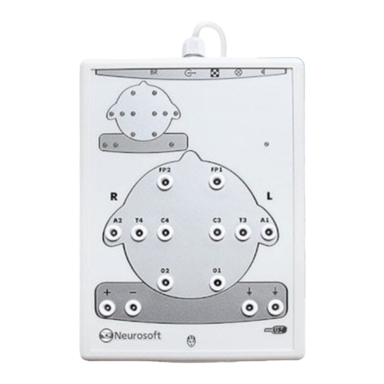
PC. 1.3. Connectors and Indicators The front and side panels of the Neuron-Spectrum-1/V system are shown in Fig. 2 and Fig. 3. The touch-proof connectors for electrode cables attachment, LED operation indicator and impedance indicators are located on the front panel (Fig. -
Page 11: Labeling
PC via USB cable. Other connectors are designed for other stimulators (not for veterinary use). Fig. 3. Top side panel of Neuron-Spectrum-1/V. 1.4. Labeling The example of labeling of the electronic unit is shown in Fig. 4. - Page 12 Neuron-Spectrum-1/V (Technical Manual) ingress protection according to IEC 60529 (EN 60529). – number according to catalogue by ISO 15223-1. – serial number by ISO 15223-1. – date of manufacture by ISO 15223-1. – manufacturer’s name and address by ISO 15223-1.
-
Page 13: Assembly And Installation
Assembly and Installation Assembly and Installation 2.1. Requirements to Personnel The assembly and installation of the system should be carried out by a person who is empowered by the manufacturer or technical personnel of the medical institution which is going to use it. Remember, that the accuracy of system mounting defines the safety and quality of its operation. -
Page 14: Unpacking And Check Of Delivery Set
Check the system components and make sure that there is no external damage. 2.4. System Assembly and Connection Place the computer and electronic unit of the Neuron-Spectrum-1/V system according to your plan and connect the computer equipment according to the operational docu- mentation for them. - Page 15 Assembly and Installation The connection of the Neuron-Spectrum-1V system to PC is shown in Fig. 6. Fig. 6. Connection to PC. Insert the USB cable connector into the USB socket of the computer system unit. The system must be connected to the USB port on the system unit or to USB hub powered from the mains.
-
Page 16: Proper Use
Neuron-Spectrum-1/V (Technical Manual) Proper use 3.1. Getting Ready Operating Limitations: Ambient temperature is from +10 to +35С. Relative humidity is from 30 to 85% (non-condensing). Atmospheric pressure is from 70 to 106 kPa. Before the power supply is switched on, make sure that the electronic unit and com- puter equipment cases have no apparent mechanical failures which can represent danger. -
Page 17: Troubleshooting
Reinstall the software from the electronic media. No EEG acquisition in the The incorrect connection of 1. Check the connection of monitoring mode the system. the system to the PC. 2. Contact Neurosoft service center. -
Page 18: Actions In Emergency
Neuron-Spectrum-1/V (Technical Manual) Table 2. Continued Trouble Cause Way of Removal When the starting program, 1. The database directory is 1. Check the PC connection the Database connection not available. to the local network. Make error message appears on the 2. -
Page 19: Maintenance
4.3. Disinfection Before cleaning the electronic unit, switch it off. As you clean, visually inspect the unit and its components for damage or wear. Contact Neurosoft if you notice damage to the exterior of the component. For routine cleaning of the electronic unit, use a cloth gently wrung in phenoles (Bacil- lotex®... -
Page 20: Current Repair
Neuron-Spectrum-1/V (Technical Manual) moistened with disinfectant (for example, 1% chloramine solution or 3% hydrogen per- oxide solution). The use of organic solvents and aromatic oils must be avoided. Never submerge the device or the cables in disinfectant or other liquids. -
Page 21: Photic Stimulator
The system and its accessories should not be disposed of in general waste. The sys- tem disposal should be performed according to your local regulations. Delivery Set and Package Data The Neuron-Spectrum-1/V veterinary digital EEG system is collected and packed. The system is ready for operation. Package report number ________________... -
Page 22: Warranty
8.4. The manufacturer is obliged to repair the system in case of its breakdown during the warranty period free of charge. The repair is carried out in Neurosoft service cen- ter (5, Voronin str., Ivanovo, 153032, Russia) in compliance with the procedure stated in chapter 9 “Reclamation”. -
Page 23: Reclamation
9.1. In case of system breakdown or faultiness in the period of warranty and also product defect detected when primary acceptance, the consumer should send written notification to Neurosoft. This notification should contain the following information: customer’s name and address;... -
Page 24: Annex 1. Delivery Set
Neuro-Audio/V (Technical Manual) Annex 1. Delivery Set The base delivery set for the veterinary digital EEG system Neuron-Spectrum-1/V is given in Table 3. Table 3. Base Delivery Set Order code or Name Quantity, pcs Main Specifications NS015201.041-022 Neuron-Spectrum-1 electronic unit NS016201.038... -
Page 25: Annex 2. Electromagnetic Emissions And Immunity
Annex 2. Electromagnetic Emissions and Immunity Annex 2. Electromagnetic Emissions and Immunity Guidance and manufacturer’s declaration – electromagnetic emissions The system is intended for use in the electromagnetic environment specified below. The customer or the user of the system should assure that it is used in such an environment. Electromagnetic environment —... - Page 26 Neuro-Audio/V (Technical Manual) Guidance and manufacturer’s declaration – electromagnetic immunity The system is intended for use in the electromagnetic environment specified below. The customer or the user of the system should assure that it is used in such an environment. IEC 60601 test Electromagnetic Immunity test...
- Page 27 Annex 2. Electromagnetic Emissions and Immunity Guidance and manufacturer’s declaration – noise immunity The system is intended for operation in electromagnetic conditions environment described below. The customer or user of the system should provide the system operation in the specified electromagnetic conditions environment.
- Page 28 Neuro-Audio/V (Technical Manual) Recommended separation distances between portable and mobile RF communications equipment and the system The system is intended for use in an electromagnetic environment in which radiated RF disturbances are controlled. The customer or the user of the system can help prevent electromagnetic interference by maintaining a minimum distance between portable and mobile RF communications equipment (transmitters) and the system as recommended below, according to the maximum output power of the communications equipment.
Need help?
Do you have a question about the Neuron-Spectrum-1/V and is the answer not in the manual?
Questions and answers