
Subscribe to Our Youtube Channel
Related Manuals for Fukuda CardiMax Series


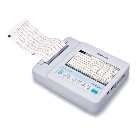
Summary of Contents for Fukuda CardiMax Series
- Page 1 Service Manual ELECTROCARDIOGRAPH * Before installation/maintenance, read this service manual thoroughly. * After reading this service manual, store it in a safe place.
- Page 2 2017 Fukuda Denshi Co., Ltd. © No part of this document may be reproduced or transmitted in any form without the prior written permission of Fukuda Denshi Co., Ltd. If this manual has pages missing or out of order, contact Fukuda Denshi for replacement.
- Page 3 bl5928 Model Name FX-8200 Service Manual Revision History Edition Revised Items Reason of the Revision Revised Date New Edition June, 2017...
-
Page 5: Table Of Contents
Contents Contents Preface Preface ............................i About This Manual ........................i Composition of This Manual.........................i Reminders to Use the Equipment Safely.................i Safety Notations ..........................ii An Example of Safety Symbol......................ii Labels for Assuring Safety ......................... iii Symbols on the Equipment ........................ iii Safety ..............................iv Precautions when Using with Other Equipment ................. - Page 6 Contents Block Diagram ........................3-1 Pin Arrangement of External Connector ................3-2 Chapter 4 Spare Parts List Chapter 5 Disassembly and Assembly Procedure Power Supply Block......................5-1 Paper Tray Block ........................ 5-1 Recorder Block (1/3)......................5-2 Recorder Block (2/3)......................5-3 Recorder Block (3/3)......................
- Page 7 Contents Trouble at Startup..........................7-4 Trouble during Operation ........................ 7-5 Chapter 8 Maintenance Self-Diagnosis (User Maintenance)..................8-1 User Maintenance Menu ......................... 8-1 Test Pattern Waveform ........................8-1 Date/Time............................8-2 Status Display ..........................8-3 General Test 1..........................8-3 General Test 2..........................8-5 Key Test ............................
- Page 8 Contents Touch Current..........................9-7 Patient Leakage Current (From Patient Connection to Ground)............9-7 Patient Leakage Current (When external voltage is applied to SIP/SOP) ........9-7 Patient Leakage Current (When external voltage is applied to patient connection of Type F Applied Part) ..............................
- Page 9 Contents Preface Preface .....................i About This Manual................i Composition of This Manual ............... i Reminders to Use the Equipment Safely..........i Safety Notations ................ii An Example of Safety Symbol ............ii Labels for Assuring Safety..............iii Symbols on the Equipment..............iii Safety ....................iv Precautions when Using with Other Equipment .......
- Page 10 Contents...
-
Page 11: Preface
Preface bl5988 This manual contains technical information of the CardiMax series FX-8200 (hereinafter referred to as FX-8200) intended for Fukuda Denshi service representatives and professional engineers. Before performing maintenance or troubleshooting of the equipment, read the manual thoroughly to ensure proper and safe use of the equipment. -
Page 12: Safety Notations
When removing the casing and working, it is necessary to check the safety items after assembly. When removing the casing and working, please contact the concerned department at the head office (Fukuda Denshil Service). Please use the device on the desk with static electricity countermeasures to prevent damage to electric parts due to static electricity. -
Page 13: Labels For Assuring Safety
Preface Reminders to Use the Equipment Safely Labels for Assuring Safety bl5635 Warning (safety) labels are attached to this device to indicate precautions that need to be followed to ensure proper and safe use of the device. Make sure to follow the instructions of the warning labels attached to this device when operating the device. -
Page 14: Safety
Preface Reminders to Use the Equipment Safely Safety bl5637 Design Specifications This equipment meets the requirements of IEC 60601-1(2005) +Am1(2012) "Medical electrical equipment – Part 1: General requirements for basic safety and essential performance" and is classified as follows. 1 Protection against electrical shock Class I, Internally Powered Device 2 Degree of protection against electrical shock... -
Page 15: Optional Accessories
Connect so that all equipments satisfy the conditions of operating environment. Only the peripheral devices and cables specified by Fukuda Denshi should be connected to this equipment using the specified procedure. For details of the connection procedure, contact your local Fukuda Denshi service representative. -
Page 16: Application To Heart
Preface Reminders to Use the Equipment Safely Application to Heart bl5645 CAUTION This equipment is a type CF applied part, but it is not intended for direct applications to patients' heart. Connecting the Power Cable bl5648 WARNING When operating this device using an AC power supply, make sure to connect the power cable to 100/240 V AC hospital grade outlet. - Page 17 Do not drop the equipment or subject it to strong impact or vibration. It may result in electric shock or a fire hazard. Contact your local Fukuda Denshi service representative if this equipment is dropped or damaged. Do not subject the LCD screen to strong impact. Doing so may cause damage.
-
Page 18: Precautions Concerning The Lan
USB Memory Use a media specified by Fukuda Denshi. Using unspecified media may cause failure to the equipment, such as damage or loss of ECG data. The warranty does not cover data retrieval or repair that is required when problems such as these are caused by using unspecified items. -
Page 19: Storage, Transportation, And Disposal
Be careful not to let liquid such as alcohol get into the equipment. Transportation CAUTION Pack this device in packaging specified by Fukuda Denshi when transporting. The device does not have handles. Carry it by holding it with both hands. -
Page 20: Cleaning And Disinfection
Preface Reminders to Use the Equipment Safely Disposing the Equipment WARNING When disposing of this device and accessories, commission disposal to a specialist waste disposal contractor. Cleaning and Disinfection bl5654 WARNING Electrodes, Lead Cables Disinfect the electrodes and lead cables between uses by wiping with cotton or a cloth soaked in an alcohol solution.Then, wipe with a soft cloth. -
Page 21: Emc Guidance
Preface Reminders to Use the Equipment Safely Malfunctions may be caused by the discharge of static electricity in dry environments (rooms), such as in winter. Humidify the room, or discharge the static electricity from the operator and the patient before using the equipment. - Page 22 Preface Reminders to Use the Equipment Safely Compliance to the Electromagnetic Immunity (1) The FX-8200 is intended for use in the electromagnetic environment specified below. The customer or the user of the FX-8200 should verify that it is used in such an environment. IEC 60601-1-2 Immunity Test IEC 60601-2-25...
- Page 23 Preface Reminders to Use the Equipment Safely Compliance to the Electromagnetic Immunity (2) The FX-8200 is intended for use in the electromagnetic environment specified below. The customer or the user of the FX-8200 should verify that it is used in such an environment. IEC 60601-1-2 Compliance Immunity Test...
- Page 24 Preface Reminders to Use the Equipment Safely Interference by Electrosurgical Instrument This equipment is protected against any malfunctions that may be caused by the usage with the electrosurgical instrument specified below. Immunity IEC 60601-2-25 Compliance Level Electromagnetic Environment/Guidance Test Test Level Incision mode Output power 300 W...
-
Page 25: Chapter 1 General Description
Chapter 1 General Description Contents Chapter 1 General Description Features of this ECG ..............1-1 Names of Parts and Their Functions ........... 1-1 Types and Functions of Operation Panel Keys ......1-4 Specifications ................1-5... - Page 26 Chapter 1 General Description Contents...
-
Page 27: Features Of This Ecg
Chapter 1 General Description bl5993 This chapter explains the overview of CardiMax Series FX-8200, the name of each part and the specifications. Features of this ECG bl5671 The CardiMax series FX-8200 measures a standard 12-lead electrocardiogram (ECG) with high accuracy and performs processing of classification of findings. - Page 28 Chapter 1 General Description Names of Parts and Their Functions Front view Rear view, bottom view 1 Paper tray The recording paper is loaded inside. 2 Thermal head Prints ECG waveforms and measurement values on the recording paper. 3 AC Power Indicator (Blue) When connected to an AC outlet, the indicator will light.
- Page 29 Chapter 1 General Description Names of Parts and Their Functions NOTE To ensure the necessary air flow, do not block these vents. A minimum space of 5 cm is required between the back/sides of the equipment and the wall. 8 ECG connector (ECG waveform input) Connects the ECG patient cable.
-
Page 30: Types And Functions Of Operation Panel Keys
Chapter 1 General Description Types and Functions of Operation Panel Keys Types and Functions of Operation Panel Keys bl5675 The operation panel buttons are used for operation. The function of each button on the operation panel is as follows: 1 Power Supply Key Turns ON/OFF the power. -
Page 31: Specifications
Chapter 1 General Description Specifications Specifications bl5882 Control Panel Power key, START/STOP key, Review key, Reset Key, 1 mV key, Leady key, Sensitivity key Standard sensitivity 10 mm/mV Sensitivity changes 1/4, 1/2, 1, 2, Auto Stability of sensitivity Temporal change within ±3% Accuracy of Sensitivity: Error: +/- 5% Detection range/accuracy of heart rate... - Page 32 Chapter 1 General Description Specifications Analysis Processing Unit Patient Information ID number, age, gender, height, weight, etc. Basic Measurement Heart rate, RR, PR, QRS, QT time, QTcB, QTcF, electric axis, SV1, RV5 (6) Interpretations and Codes Approximately 130 types Minnesota Code Approximately 130 types Grade Judgment...
-
Page 33: Chapter 2 Operational Description
Chapter 2 Operational Description Contents Chapter 2 Operational Description Hardware Overview ..............2-1 Operational Description ............... 2-1 Primary Power Source..............2-1 CPU Board ..................2-2 ECG Input Unit ................2-6 Operation Panel/Touch Panel Unit ..........2-6... - Page 34 Chapter 2 Operational Description Contents...
-
Page 35: Hardware Overview
Chapter 2 Operational Description Hardware Overview Chapter 2 Operational Description Hardware Overview bl5929 The ECG waveform is inputted through the lead cable and printed on the recording paper. A detailed ECG is displayed on the high-precision color LCD. An overview diagram of the FX-8200 including the optional accessories is shown below.The dashed lines indicate the optional accessories. -
Page 36: Cpu Board
Chapter 2 Operational Description Operational Description CPU Board bl5931 Overview of CPU Board The block diagram of the CPU board is shown below. CPU Board DDR2 SDRAM Bus USB x 3 i.MX515 800MHz Main Bus FPGA Flash Amp(12L) Memory Motor Driver Local... - Page 37 Chapter 2 Operational Description Operational Description Secondary Power Source The block diagram of the secondary power source circuit is shown below. The original power is supplied from the primary power source unit or battery unit. To prevent from not being able to turn ON/OFF the power caused by CPU runaway, the power ON process is performed by the hardware.
- Page 38 Chapter 2 Operational Description Operational Description Display Unit The block diagram of the display unit is shown below. RGB data Transmitter Thermal Print Head Control Unit The block diagram of the thermal print head control unit is shown below. Temperature Data Print Data...
- Page 39 Chapter 2 Operational Description Operational Description Sensor Drive Unit The block diagram of the sensor drive unit is shown below. Detection Threshold Signal Compare Amplify Photo Transistor Sensor Drive Sensor Pulse Output Paper Paper The paper end sensor and mark sensor are controlled as follows. The sensor drive pulse is output from the FPGA and input to the phototransistor via buffer.
-
Page 40: Ecg Input Unit
Chapter 2 Operational Description Operational Description ECG Input Unit bl5932 The functional block diagram of the ECG input unit is shown below. AMP Block Input Differential Photo Isolator A/D Converter Protector Amplifier CPU Block +5VF +2.5VA Isolation Power 100KHz Patient -2.5VA 20bit A/D Input... -
Page 41: Chapter 3 Wire Connection Diagram/Block Diagram
Chapter 3 Wire Connection Diagram/Block Diagram Contents Chapter 3 Wire Connection Diagram/Block Diagram Wire Connection Diagram............3-1 Block Diagram ................3-2 Pin Arrangement of External Connector ........3-3... - Page 42 Chapter 3 Wire Connection Diagram/Block Diagram Contents...
-
Page 43: Wire Connection Diagram
Chapter 3 Wire Connection Diagram/Block Diagram Wire Connection Diagram Chapter 3 Wire Connection Diagram/ Block Diagram Wire Connection Diagram bl5934 The connection diagram of FX-8200 is shown below. TO ALTERA PCB-7798 TRAY UP TRAY UP SENS... - Page 44 Driver CAUTION To repair a connector or cable, replace the entire board or contact your local Fukuda Denshi factory for service. Parts may be damaged when repairing/detaching connectors on the board as they are very small and pin-pith is very narrow. Repair or removal of the connector may damage the board, connectors and parts.
-
Page 45: Pin Arrangement Of External Connector
Chapter 3 Wire Connection Diagram/Block Diagram Pin Arrangement of External Connector Pin Arrangement of External Connector bl5936 CN8 LAN Model: SS-640810-A-NF-A111 Pin No. Signal Name Remarks TXD+ 10 BASE-T transmission differential data + (output) TXD- 10 BASE-T transmission differential data - (output) RXD+ 10 BASE-T received differential data + (output) RXD-... - Page 46 Chapter 3 Wire Connection Diagram/Block Diagram Pin Arrangement of External Connector CN12 Serial Model: DF13C-4P-1.25V(51) Pin No. Signal Name Remarks Received data (input) Transmitt data (output) Ground (DG) CN15 ECG Model: RDAG1-15SE1 Pin No. Signal Name Remarks Chest C2 Chest C3 Chest C4 Chest C5...
-
Page 47: Chapter 4 Spare Parts List
Chapter 4 Spare Parts List Contents Chapter 4 Spare Parts List... - Page 48 Chapter 4 Spare Parts List Contents...
- Page 49 Chapter 4 Spare Parts List Chapter 4 Spare Parts List bl6682 The following is the spare parts list. Parts Number Item Name Model Type, Standard, Remarks Q'ty 1E010886* LCD Touch Panel RFF70ZG-AIW-DNS 1T010131* Power Supply Unit SNP-GK65-MG 1Y001203* Motor PFC25-24Q1G (1/50) -02 1W003030* Thermal Print Head AE108-8E701...
- Page 50 Chapter 4 Spare Parts List Parts Number Item Name Model Type, Standard, Remarks Q'ty 6C015692* Gear A 1Z010341* One-way Clutch OWC307GXLZ 6C015693* Static-Eliminator Felt 6C015694* Paper Tray 9H011503* Push Button SU 6C015696* Spring for Buttons 6C015697* Shaft for Hook Attachment 9H011504* Paper Support SU 6C015699*...
-
Page 51: Chapter 5 Disassembly And Assembly Procedure
Chapter 5 Disassembly and Assembly Procedure Contents Chapter 5 Disassembly and Assembly Procedure Power Supply Block..............5-1 Paper Tray Block ................. 5-2 Recorder Block (1/3)..............5-3 Recorder Block (2/3)..............5-4 Recorder Block (3/3)..............5-5 Upper Case Block (1/2) ............... 5-6 Upper Case Block (2/2) ............... - Page 52 Chapter 5 Disassembly and Assembly Procedure Contents...
-
Page 53: Power Supply Block
Chapter 5 Disassembly and Assembly Procedure Power Supply Block Chapter 5 Disassembly and Assembly Procedure Power Supply Block bl6735 2-Double washer sems M3 x 8 2-M6 Nut Potential Equalization Terminal Cover Grounding Plug POAG-S6-15 Common with FX-8222 Cable between power supply and CPU board AC Inlet Cable Power Supply Unit SNP-GK65-MG Power Supply Plate... -
Page 54: Paper Tray Block
Chapter 5 Disassembly and Assembly Procedure Paper Tray Block Paper Tray Block bl6736 2-E-type retaining rings Nominal diameter 3 2-E-type retaining rings Nominal diameter 4 Paper Support SU Platen Roll Gear B DDL-1150ZZRP0P25LY551 Shaft for Hook Attachment Spring for Buttons Push Button SU Hook Paper Tray... -
Page 55: Recorder Block (1/3)
Chapter 5 Disassembly and Assembly Procedure Recorder Block (1/3) Recorder Block (1/3) bl6738 2-Double washer sems M2.6 x 5 Glass cloth adhesive tape_No.188UL_Width 10mm x Length 55mm 2-Double washer sems M3 x 8 E-type retaining ring Nominal designation 2 2-Double washer sems M3 x 6 E-type retaining ring Nominal designation 2.5 2-Double washer sems M2.6 x 5... -
Page 56: Recorder Block (2/3)
Chapter 5 Disassembly and Assembly Procedure Recorder Block (2/3) Recorder Block (2/3) bl6739 2-Double washer sems M2.6 x 5 2-Double washer sems M2.6 x 5 BSB-2607 Brass Spacer (Hexagon) Hook Holder (B) Hook Holder (A) SU Mark Sensor/Paper Tray Up Sensor Cable ASSY 1 Paper Guide Paper Case SU Item/Model Type... -
Page 57: Recorder Block (3/3)
Chapter 5 Disassembly and Assembly Procedure Recorder Block (3/3) Recorder Block (3/3) bl6740 Tool: Phillips Screwdriver #2 2-Flat head screws M3 x 6 Double washer sems M2.6 x 5 Double washer sems M2.6 x 5 2-E-type retaining rings Nominal designation 3 Paper Cutter Paper Tray Attachment Shaft Recorder Block (2/3) -
Page 58: Upper Case Block (1/2)
Chapter 5 Disassembly and Assembly Procedure Upper Case Block (1/2) Upper Case Block (1/2) bl6741 P-type Nominal designation 3 x 10 P-type Nominal designation 3 x 10 4-P-type Nominal designation 3 x 10 Core HF70SH41X08X12 Shielding Gaskets STGPF2-10 (8 mm) LCD Lid (100 mm) LCD Lid (162 mm) LCD Support Plate... -
Page 59: Upper Case Block (2/2)
Chapter 5 Disassembly and Assembly Procedure Upper Case Block (2/2) Upper Case Block (2/2) bl6742 3-P-type Nominal designation 3 x 10 3-P-type Nominal designation 3 x 10 Double washer sems M3 x 8 Shielding Gaskets STGPF8-8 (10 mm) ECG Shield Cover PCB-7785 ASSY Recorder Shield Plate Recorder Block (3/3) -
Page 60: Lower Case Block
Chapter 5 Disassembly and Assembly Procedure Lower Case Block Lower Case Block bl6744 2-P-type Nominal designation 3 x 10 2-Double washer sems M3 x 8 Screw Retaining Washer TM-147-1 Rubber Foot Cushioning Material (32 x 65) Battery Cover Recorder Sheet Paper Sheet Lower Case SU Item/Model Type... -
Page 61: General Assembly Diagram
Chapter 5 Disassembly and Assembly Procedure General Assembly Diagram General Assembly Diagram bl6745 5-P-type Nominal designation 3 x 10 FX-8200 (EXP) Rating Label (with number assigned) Follow Operating Instructions Mark Label Caution Mark Label Caution Label (Battery) Lower Case Block Upper Case Block (2/2) Item/Model Type Q'ty... -
Page 62: External Appearance
Chapter 5 Disassembly and Assembly Procedure External Appearance External Appearance bl5947 260 ± 10 mm 5-10... -
Page 63: Removing The Lower Case
Chapter 5 Disassembly and Assembly Procedure Removing the Lower Case Removing the Lower Case bl5948 Tool: Phillips Screwdriver #2 Remove five screws (P-tight with washer head, M3x10) on the bottom side of the main unit, and remove the lower case. Removing the Recorder Block bl5950 Tool: Phillips Screwdriver #2... -
Page 64: Removing The Cpu Board
Chapter 5 Disassembly and Assembly Procedure Removing the CPU Board Remove four screws (P-tight with washer head, M3x10), and remove the recorder block. Removing the CPU Board bl5949 Tool: Phillips Screwdriver #2 Disconnect the flexible cables connected to the CPU board. (Key Sheet Flexible Cable, LCD Flexible Cable, Touch Panel Flexible Cable) 5-12... - Page 65 Chapter 5 Disassembly and Assembly Procedure Removing the CPU Board Remove five screws (P-tight with washer head, M3x10). Lift up the CPU board to disconnect the cable between power supply and CPU board, and remove the CPU board. 5-13...
-
Page 66: Removing The Power Supply Unit
Chapter 5 Disassembly and Assembly Procedure Removing the Power Supply Unit Removing the Power Supply Unit bl5951 Tool: Phillips Screwdriver #2 Remove one screw (P-tight with washer head, M3x10), and remove the power supply part. Remove two screws (double washer sems M3x8) and remove the power supply unit. Removing the LCD bl5953 Tool: Phillips Screwdriver #2... -
Page 67: Chapter 6 Software Update
Chapter 6 Software Update Contents Chapter 6 Software Update Software Updating Procedure ............. 6-1... - Page 68 Chapter 6 Software Update Contents...
-
Page 69: Software Updating Procedure
Chapter 6 Software Update Software Updating Procedure Chapter 6 Software Update Software Updating Procedure bl5954 The software can be updated using the USB memory. CAUTION Never unplug the USB memory while updating the software. It may cause a malfunction of the main unit or USB memory, or software update may not be possible. - Page 70 Chapter 6 Software Update Software Updating Procedure...
-
Page 71: Chapter 7 Troubleshooting
Chapter 7 Troubleshooting Contents Chapter 7 Troubleshooting When Malfunction Occurs ............7-1 When the ECG Waveform is Unstable ...........7-1 When the Equipment does not Operate .........7-1 Messages and Remedies ............7-2 Battery ....................7-2 File....................7-3 Hardware Trouble ................ 7-3 Trouble at Startup................7-4 Trouble during Operation..............7-5... - Page 72 Chapter 7 Troubleshooting Contents...
-
Page 73: When Malfunction Occurs
Chapter 7 Troubleshooting When Malfunction Occurs Chapter 7 Troubleshooting When Malfunction Occurs When the ECG Waveform is Unstable bl5955 When the ECG waveform is unstable, check the following items. Is the place of examination appropriate? Is there noise generating electrical devices such as x-ray devices or ultrasound devices nearby? If there is, turn OFF the power of those devices or select another place for examination. -
Page 74: Messages And Remedies
Chapter 7 Troubleshooting Messages and Remedies NOTE Except for the case when the trouble is caused by the external equipment, it is recommended to disconnect the external equipment for smooth troubleshooting. Messages and Remedies bl5957 FX-8200 displays various messages during operation, and prompts the operator for confirmation See [FX-8200 Operation Manual] for details of each message. -
Page 75: File
<Failed to format (Media).> Formatting of the media has failed. The failure of the media can be considered. Contact your local Fukuda Denshi service representative. <There is not enough space on There is not enough space on the media to Replace with a media with enough capacity. -
Page 76: Trouble At Startup
Chapter 7 Troubleshooting Hardware Trouble Do not insert or remove cables with wet hands.This may cause electric shocks, short circuiting or injury. NOTE The "Possible Cause" listed on the following pages are not necessarily the actual causes. Various malfunctions may be combined. After repairing, make sure to perform safety check and operation check. -
Page 77: Trouble During Operation
Chapter 7 Troubleshooting Hardware Trouble Trouble during Operation bl5960 ECG Data Symptom Possible Cause Malfunctioning Part Solution The ECG waveform is in ECG Data Receiving Circuit PCB-7785 Replace the PCB-7785 the baseline position. (All Failure (9F0110900). leads) ECG Amp Power Failure ECG Amp Power Supply Replace the PCB-7785 Circuit... - Page 78 Chapter 7 Troubleshooting Hardware Trouble Printing Symptom Possible Cause Malfunctioning Part Solution Printing is not performed. Cable Disconnection Thermal Cable (28P) Replace the thermal print head (1W003030A). FPGA Failure FPGA Replace the PCB-7785 (9F0110900). Thermal Print Head Failure Thermal Print Head Replace the thermal print head (1W003030A).
- Page 79 Chapter 7 Troubleshooting Hardware Trouble Other Symptom Possible Cause Malfunctioning Part Solution Buzzer tone is difficult to Buzzer Failure Buzzer Replace the PCB-7785 recognize. (or is not (9F0110900). generated.) Buzzer Circuit Failure Buzzer Circuit Replace the PCB-7785 (9F0110900). Clock, calendar is not The backup battery is depleted.
- Page 80 Chapter 7 Troubleshooting Hardware Trouble...
-
Page 81: Chapter 8 Maintenance
Chapter 8 Maintenance Contents Chapter 8 Maintenance Self-Diagnosis (User Maintenance) ..........8-1 User Maintenance Menu ..............8-1 Test Pattern Waveform..............8-1 Date/Time ..................8-2 Status Display.................8-3 General Test 1................8-4 General Test 2................8-5 Key Test ..................8-6 Sound Test ..................8-6 Screen Test ..................8-7 Touch Panel Test ................8-7 Thermal Printing Test ..............8-7 I/O Test...................8-8 LCD Brightness Adjustment ............8-9... - Page 82 Chapter 8 Maintenance Contents...
-
Page 83: Self-Diagnosis (User Maintenance)
Chapter 8 Maintenance Self-Diagnosis (User Maintenance) Chapter 8 Maintenance Self-Diagnosis (User Maintenance) bl5961 There are following items on the user maintenance menu. Simulator Waveform Set Date/Time Display Status General Test 1 General Test 2 Key Test Sound Test LCD test Thermal Printing Test Touch Panel Test I/O Test... -
Page 84: Date/Time
Chapter 8 Maintenance Self-Diagnosis (User Maintenance) The test pattern can be selected from the following 5 patterns. Pattern Description Pattern 1 Normal Waveform Pattern 2 Myocardial Infarction Pattern 3 Extrasystole Pattern 4 Brugada Type Pattern 5 Brugada Risk Touch [Back] > [Back] > [To exam] to return to the examination screen. ... -
Page 85: Status Display
Chapter 8 Maintenance Self-Diagnosis (User Maintenance) Set the year, month, day, time, and touch [ Status Display bl5965 Battery status, etc. can be checked. Select [Status Display] on the "Maintenance" menu. The status screen will be displayed. Touch [Back] > [Back] > [To exam] to return to the examination screen. -
Page 86: General Test 2
Chapter 8 Maintenance Self-Diagnosis (User Maintenance) General Test 1 bl5966 Test the LCD, touch panel, key/LED, sound, and status. Select [General Test 1] on the "Maintenance" menu. The "General Test 1" screen will be displayed. Press the (Start/Stop) key on the operation panel. ... -
Page 87: General Test 2
Chapter 8 Maintenance Self-Diagnosis (User Maintenance) To end the sound test, touch [Next]. On the status screen, check each status. Touch [Back] > [Back] > [To exam] to return to the examination screen. General Test 2 bl5967 Test the recording, memory, external I/O. Select [General Test 2] on the "Maintenance"... -
Page 88: Key Test
Chapter 8 Maintenance Self-Diagnosis (User Maintenance) If the judgement is "NG" for any of the test items, "NG" will be displayed for "General". Touch [Back] > [Back] > [To exam] to return to the examination screen. Key Test bl5968 Test the key operation. -
Page 89: Screen Test
Chapter 8 Maintenance Self-Diagnosis (User Maintenance) Screen Test bl5970 Test the display. Select "Display Test" from Maintenance Menu Screen. When selected, the screen switches in the order red -> green -> blue -> ash. Make sure there are no missing dots or color unevenness. You can return to the test screen by [Return] ->... -
Page 90: I/O Test
Chapter 8 Maintenance Self-Diagnosis (User Maintenance) Selecting the printing speed and pattern will start the printing. Check the printing speed, and check that there are no phase shift, missing dots, or uneven colors. I/O Test bl5973 Test the I/O operation. Select [I/O Test] on the "Maintenance"... -
Page 91: Lcd Brightness Adjustment
Chapter 8 Maintenance Self-Diagnosis (Manufacturer Maintenance) LCD Brightness Adjustment bl5974 Adjust the LCD brightness. Select [Adjust LCD Brightness] on the "Maintenance" menu. The screen to adjust the LCD brightness will be displayed. Touch the arrows to adjust the brightness. ... -
Page 92: Amp Status
Chapter 8 Maintenance Self-Diagnosis (Manufacturer Maintenance) On the manufacturer maintenance menu, select an item. AMP Status bl5977 Check the AMP status. On the manufacturer maintenance menu, select [AMP Status]. Adjust Perforations bl5978 Adjust the recording paper perforation position. On the manufacturer maintenance menu, select [Adjust perforations]. Touch the right and left arrows to adjust the perforation position. -
Page 93: Mac Address
Chapter 8 Maintenance Self-Diagnosis (Manufacturer Maintenance) MAC Address bl5979 Touch [MAC Address] to open the "MAC Address" screen. This setting is not necessary as it is factory-configured. Adjust Touch Panel bl5980 Touch the center part of "+" displayed on the screen. Screen Capture bl5981 The hard copy function can be enabled/disabled.When enabled, the displayed screen can be saved on the USB... -
Page 94: Backup Battery Replacement
Chapter 8 Maintenance Backup Battery Replacement Backup Battery Replacement bl5982 The backup battery can be replaced by removing the lower case. After the replacement, make sure that "OK" is displayed on the status display area of the maintenance menu. Tool: Phillips Screwdriver #2 Remove the lower case block. -
Page 95: Main Battery (8Ph-4/3A3700-H-J18) Replacement
Chapter 8 Maintenance Main Battery (8PH-4/3A3700-H-J18) Replacement As shown in the following picture, insert one side of the new lithium-ion battery and push it in with finger. After the replacement, make sure that "OK" is displayed on the status display area of the maintenance menu. ... - Page 96 Chapter 8 Maintenance Main Battery (8PH-4/3A3700-H-J18) Replacement NOTE The date of manufacture is indicated on a label of the main battery. Procedure to Replace the Main Battery Tool: Phillips Screwdriver #2 Remove the 2 screws on the bottom of the battery cover, and then remove the battery cover. Take out the battery from the main unit, and disconnect the battery connector from the main unit.
-
Page 97: Replacement Of Display Unit Backlight
Chapter 8 Maintenance Replacement of Display Unit Backlight Be careful not to pinch the connection cable under the cover. Precautions for Usage of Battery Take the following precautions when using the battery. Battery Life The battery can be charged and discharged (used) for approximately 500 times. Note that the service life varies depending on the frequency of use and the charging/discharging pattern of the battery. -
Page 98: Motor Replacement
Chapter 8 Maintenance Motor Replacement Touch [Touch Panel Adjust] to switch to the next screen. Touch the center part of "+" displayed on the screen. When the next pointer is displayed, touch the pointer. When all five (5) points are touched, the touch panel adjustment will automatically end. Motor Replacement bl5985 When replacing the motor, it is necessary to remove the recorder block. -
Page 99: Thermal Print Head Replacement
Chapter 8 Maintenance Thermal Print Head Replacement Tighten the screw while verifying the gear contact. Thermal Print Head Replacement bl5986 When replacing the thermal print head, it is necessary to remove the recorder block.After the replacement, make sure to adjust the thermal recorder. Tools: Phillips Screwdriver #2, 5.5 mm Nut Driver Remove the recorder block. - Page 100 Chapter 8 Maintenance Adjusting the Thermal Recorder Loosen the screws indicated with circle marks using a 5.5 mm nut driver, and adjust the thermal print head. On the "Thermal Printing Test" menu, select the printing pattern and speed for test printing. Touch [Print Head Test] to test the print density.
-
Page 101: Cleaning And Disinfecting
CAUTION Never use sandpaper as it will damage the heating element. Contact your Fukuda Denshi representative when the thermal print head requires cleaning. Cleaning touch panel Since the display panel uses a touch panel, finger prints and other stains are likely to appear on the touch panel. -
Page 102: Cleaning The Accessories
Chapter 8 Maintenance Cleaning and Disinfecting Cleaning the Accessories bl5992 Lead cable and connection cables Wipe gently with neutral detergent or 70% isopropyl alcohol for cleaning. Do not use organic solvents such as thinner or toluene. Clip electrodes Wipe gently with neutral detergent or alcohol for cleaning. - Page 103 Chapter 9 Maintenance and Inspection Contents Chapter 9 Maintenance and Inspection Daily Check ................. 9-1 Daily Check Procedure..............9-1 Periodic Check ................9-2 Periodic Check Procedure..............9-2 Electrical Safety Inspection Procedure ........9-5 Safety Specification of this Equipment ...........9-6 Earth Leakage Current ..............9-6 Touch Current.................9-7 Patient Leakage Current (From Patient Connection to Ground) ..9-7 Patient Leakage Current (When external voltage is applied to SIP/...
- Page 104 Chapter 9 Maintenance and Inspection Contents...
-
Page 105: Chapter 9 Maintenance And Inspection
This chapter describes the maintenance and inspection procedures for this equipment. Make sure to perform daily checks and periodic checks to maintain functionality, performance and reliability. Please note that Fukuda Denshi shall not be liable for accidents arising from failure to perform maintenance and inspections. -
Page 106: Periodic Check
Chapter 9 Maintenance and Inspection Periodic Check Mechanical Check the equipment for mechanical failures while actually operating the equipment. Item Inspection Item Procedure Criteria Main Unit 1) Key Verify that key operation is smooth. Smooth operation. 2) Printer Verify that recorder operation is smooth, Smooth operation without abnormal and no abnormal sound is heard. - Page 107 Chapter 9 Maintenance and Inspection Periodic Check Appearance Visually check the following points according to the description of the table below. Item Inspection Item Procedure Criteria Main Unit 1) Enclosure Verify that there is no scratch, crack, Should be free of exterior flaws, cracks, deformation or rust on the main unit.
- Page 108 Chapter 9 Maintenance and Inspection Periodic Check Item Inspection Item Procedure Criteria Performance 1) Check clock Touch [Set Date/Time] on the maintenance Verify that the present date/time is menu screen (Refer to "Checking the Date displayed in the Clock Setting window and Time"...
-
Page 109: Electrical Safety Inspection Procedure
Chapter 9 Maintenance and Inspection Electrical Safety Inspection Procedure Other Item Inspection Item Procedure Criteria Other 1) Power supply Check whether the device can be turned The device should be turned on/off both on/off both with AC power and battery with AC power and battery power. -
Page 110: Safety Specification Of This Equipment
Chapter 9 Maintenance and Inspection Electrical Safety Inspection Procedure Maximum allowable leakage current Leakage Current Type B Type BF Type CF (Unit: mA) Normal Single Normal Single Normal Single Condition Failure Condition Failure Condition Failure Earth Leakage Current Touch Current Patient Leakage Current Direct 0.01... -
Page 111: Touch Current
Chapter 9 Maintenance and Inspection Electrical Safety Inspection Procedure Touch Current bl5870 1. Measurement wiring diagram 2. Allowable value Normal condition Single failure 0.1mA 0.5mA Patient Leakage Current (From Patient Connection to Ground) bl5871 1. Measurement wiring diagram 2. Allowable value Normal condition Single failure Direct Current... -
Page 112: Patient Leakage Current (When External Voltage Is Applied To Patient Connection Of Type F Applied Part)
Chapter 9 Maintenance and Inspection Electrical Safety Inspection Procedure 2. Allowable value Normal condition Single failure Direct Current 0.01mA 0.05 mA Alternating Current 0.01mA 0.05 mA Patient Leakage Current (When external voltage is applied to patient connection of Type F Applied Part) bl5873 1. -
Page 113: Replacement Of The Accessories
The service life may be shortened when used in high temperature, low temperature or high humidity conditions. When the battery is depleted and the message "Replace the backup battery. The clock will be reset. (For more details, contact your local Fukuda Denshi service representative.)" is displayed, replace the battery as soon as possible. - Page 114 Chapter 9 Maintenance and Inspection Replacement of the Accessories 9-10...
-
Page 115: Chapter 10 Appendix
Chapter 10 Appendix Contents Chapter 10 Appendix Combination Example of Medical and Non-Medical Equipments 10- Check List .................. 10-2 10-1... - Page 116 Chapter 10 Appendix Contents...
-
Page 117: Combination Example Of Medical And Non-Medical Equipments
Chapter 10 Appendix Combination Example of Medical and Non-Medical Equipments Chapter 10 Appendix Combination Example of Medical and Non-Medical Equipments bl5895 The general description of possible combination of different equipments in different medical environment as specified in IEC 60601-1 "Medical electrical equipment – Part 1: General requirements for basic safety and essential performance"... -
Page 118: Check List
Chapter 10 Appendix Check List Check List bl5894 Daily Check List FX-8200 Remarks Item Inspection Item Procedure, Measurement, Criteria Judgment (Repair required) Appearance External Exterior flaws, cracks, Check that flaws, cracks, deformation and OK/NG Appearance deformation, rust rust are not found on the main unit. Peeling and dirt on label and Check that peeling or dirt is not found on OK/NG... -
Page 119: Periodic Check
Chapter 10 Appendix Check List Periodic Check List FX-8200 Remarks Item Inspection Item Procedure, Measurement, Criteria Judgment (Repair required) Appearance External Exterior flaws, cracks, deformation, Check that flaws, cracks, deformation OK/NG Appearance rust and rust are not found on the main unit. -
Page 120: Earth Leakage Current
Chapter 10 Appendix Check List Remarks Item Inspection Item Procedure, Measurement, Criteria Judgment (Repair required) Maintenance Backup battery Backup Battery Voltage 2.5V and OK/NG above Clock Setting Check that correct time is displayed. OK/NG Printing Test Check that the printing paper is fed OK/NG straight. -
Page 121: Patient Leakage Current (From Patient Connection To Ground)
Chapter 10 Appendix Check List Remarks Item Inspection Item Procedure, Measurement, Criteria Judgment (Repair required) Normal Condition 0.01 mA and OK/NG below Single Failure 0.05 mA and OK/NG Condition below Alternating Current Normal Condition 0.01 mA and OK/NG below Single Failure 0.05mA and OK/NG Condition... - Page 122 Chapter 10 Appendix Check List 10-6...
- Page 123 The company and product names used in this manual are trademarks or registered trademarks of respective companies.
- Page 124 3-39-4 Hongo, Bunkyo-ku, Tokyo, Japan Tel: +81-3-5684-1455 Fax: +81-3-3814-1222 http://www.fukuda.com 4R0101440 201706...
Need help?
Do you have a question about the CardiMax Series and is the answer not in the manual?
Questions and answers