Ouellet Comfort OFEC 000 Series Installation Instructions Manual
Hide thumbs
Also See for Comfort OFEC 000 Series:
Table of Contents
Advertisement
Quick Links
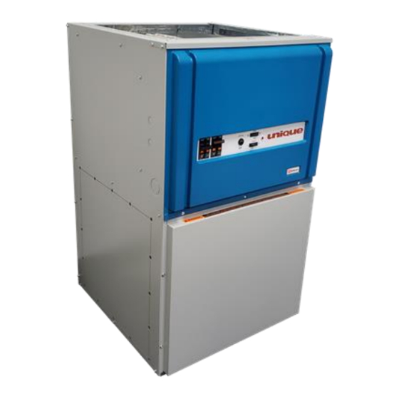
COMFORT & ADVANTAGE
INSTALLER / SERVICE TECHNICIAN:
USE THE INFORMATION IN THIS MANUAL FOR THE INSTALLATION AND
SERVICING OF THE FURNACE AND KEEP THE DOCUMENT NEAR THE UNIT
FOR FUTURE REFERENCE.
HOMEOWNER:
PLEASE KEEP THIS MANUAL NEAR THE FURNACE FOR FUTURE
REFERENCE.
Printed in Canada
Printed on 100% recycled paper
(PSC MOTOR)
Models:
Comfort
OFECxx000
Advantage
OFEAxx000
OFEAxx000-1H
Caution: Do not tamper with
the unit or its controls. Call a
qualified service technician.
Manufactured by :
Industries Dettson inc.
Sherbrooke, Québec - Canada
www.dettson.ca
www.ouellet.com
2021-11-02
1 800 463-7043
X40238 Rev. D
Advertisement
Table of Contents

Related Manuals for Ouellet Comfort OFEC 000 Series

Summary of Contents for Ouellet Comfort OFEC 000 Series
- Page 1 Manufactured by : FOR FUTURE REFERENCE. Industries Dettson inc. HOMEOWNER: Sherbrooke, Québec - Canada PLEASE KEEP THIS MANUAL NEAR THE FURNACE FOR FUTURE www.dettson.ca REFERENCE. www.ouellet.com 1 800 463-7043 X40238 Rev. D Printed in Canada 2021-11-02 Printed on 100% recycled paper...
-
Page 2: Table Of Contents
TABLE OF CONTENT 4- MAINTENANCE .......... 8 4.1- AIR FILTER ............. 8 1- SAFETY ............3 4.2- MOTOR LUBRICATION ........8 1.1- DANGER, WARNING AND CAUTION .... 3 5- FURNACE INFORMATION ......9 1.2- IMPORTANT INFORMATION ......3 1.3- DANGER OF FREEZING ........ 3 2- INSTALLATION .......... -
Page 3: 1- Safety
Never block or otherwise obstruct the filter and/or 1- SAFETY return air openings; Ask the technician installing your furnace to show and 1.1- DANGER, WARNING AND CAUTION explain to you the following items: The main disconnect switch or circuit breaker; The words DANGER, WARNING and CAUTION are used to The air filter and how to change it (check monthly identify the levels of seriousness of certain hazards. -
Page 4: Positioning The Furnace
The unit requires a 240 - 208 VAC power supply to the control Figure 1: Upflow installation panel, thermostat hook-up as shown on the wiring diagram. 2.1- POSITIONING THE FURNACE WARNING Fire and explosion hazard. The furnace must be installed in a level position, never where it will slope toward the front. -
Page 5: Conversion From Two To One Supply Wires For Models 27 Kw And More
All the 120V models (SUPxx-y120Dzz) require neutral wire 2.5- INSTALLATION OF THE THERMOSTAT because the motor works under 120VAC. A thermostat must be installed to control the temperature of the area to be heated. Follow the instructions supplied with the WARNING thermostat. -
Page 6: Anticipator Adjustment (If Required) On Thermostat Equipped With Heat Anticipator Adjustment
Figure 8: 1-stage thermostat, electric heating and air Use two elbows between each outlet and the supply and conditioning return air plenum; Cover the vertical sections of the supply and return air duct with soundproofing material; Use baffles in short radius elbows; Use flexible hangers to suspend the ducts. -
Page 7: Installation Of Accessories
2.7- INSTALLATION OF ACCESSORIES 3.2- USE OF MANUAL FURNACE CONTROLS ON ADVANTAGE FURNACE WARNING When there is a demand for heat, the pilot light (L-1) comes on. Refer to the wiring diagram. Electrical shock hazard. When the “HI/LO” switch is put into the “LO” position, it will shut Turn OFF electrical power at the fuse box or service panel down approximately half the elements. -
Page 8: Cooling Mode
The deactivation of either mode will result in the CAUTION deactivation of the corresponding relays with a delay of 0.5 second between each element. It is important to check the airflow and to ascertain that the unit does not operate above the temperatures specified in 3.3.2- Cooling mode the Technical Specifications (Table 2). -
Page 9: 5- Furnace Information
5- FURNACE INFORMATION Model: Serial number: Furnace installation date: Service telephone # - Day: Night: Service technician name and address: START-UP RESULTS Voltage: Total current consumed by the elements: Supply air temperature: Return air temperature: Supply air duct static pressure: Return air duct static pressure: Total pressure: Calculated air flow:... -
Page 10: Table 2: Technical Specifications
Table 2: Technical specifications OFECxx000 / OFEAxx000 OFEAxx000-1H RATINGS AND PERFORM ANCE 1/3 HP / 240V M otor 1 HP / 240V M otor Capacity Power, total @ 240V / 208V (Kw) 10 / 7.5 15 / 11.3 18 / 13.5 20 /15 23 / 17.3 25 / 18.8... -
Page 11: Table 3: Airflow (Cfm) - U
Table 3: Airflow (CFM) - U with 1/3 HP motor NIQUE Blower External static pressure (inche of W.C.) speed 1160 1150 1130 1110 1060 1015 HIGH 1380 1350 1295 1240 1180 1120 1060 Airflow values in cubic feet per minute (CFM) rounded to the nearest 5 CFM Data taken with air filter in place. -
Page 12: Figure 12 : Electrical Diagram, U
Figure 12 : Electrical diagram, U Comfort PSC NIQUE... -
Page 13: Figure 13 : Electrical Diagram, U
Figure 13: Electrical diagram, UNIQUE Advantage PSC... -
Page 14: Figure 14: Parts List, U
Figure 14: Parts list, U Comfort PSC NIQUE... -
Page 15: Comfort Psc
Table 5: Parts list, U Comfort PSC NIQUE Item Description Comments OFE-B04431 Acoustic insulation OFE-B04343-03 Left side panel assembly Left panel, items 3 and 1 included OFE-B04340-02 Left side panel insulation OFE-B04344-01 Back panel assembly OFE-B04341 Top back panel insulation OFE-B04343-01 Right side panel assembly Right panel, items 7 and 1 included OFE-B04340-01 Right side panel insulation... -
Page 16: Figure 15: Parts List, U
Figure 15: Parts list, U Advantage PSC NIQUE... -
Page 17: Table 6: Parts List, Unique
Electrical sequencer kit OFE 15kw 25 OFE-B04297 Electrical sequencer kit OFE 10kw 26 OFE-B04275 Plastic top door 27 OFE-X50053 Label logo Ouellet 28 OFE-B04349 Bottom door assembly 29 OFE-X00505 Label warning remove screw 30 OFE-B04356-04 Blower assembly 1hp (240v-PSC) OFE 23/25/27/30kw...
Need help?
Do you have a question about the Comfort OFEC 000 Series and is the answer not in the manual?
Questions and answers