Table of Contents
Advertisement
Quick Links
SETUP & OPERATION MANUAL
FEATURES
Heavy-duty massive router lift with 9 1/4" x
11 3/4" aluminum top plate.
Stable 4 post/lift screw design & chain drive
lifting system controlling all 4 corners simul-
taneously.
Fits all fixed base router motors*.
Smooth above-the-table adjustment mech-
anism for fast tool changes & precision bit
setting.
Available with table in either cast-iron (40-
200C), MDF (40-200M) or Phenolic (40-200P).
Stand made of tubular steel, includes,
mobility kit, adjustable leveling feet and
easy access on/off safety switch with
removable lock-out key.
Fence has 2 1⁄4" dust collection outlet and
adjustable scales.
Under table steel dust enclosure with
access door, adjustable air vent, power
cord grommet and 4" dust port with 2 1⁄4"
branch inlet to the fence. Includes 2 1⁄4"
dust hose and 2 hose clamps.
*
Some router models may require reducer
collars/adaptors.
SPECIFICATIONS
OVERALL DIMENSIONS
35 1/2" X 24" X 41" (902 X 609 X 1041 MM)
TABLE SIZE/HEIGHT
32" X 24" (812 X 609 MM) /36 1/2" (927 MM)
FENCE SIZE (EACH)
3" X 17 3/4" X 3/4" (76 X 451 X 19 MM)
MAXIMUM FENCE TRAVEL
9" (229 MM)
DUST OUTLET
4" (102 MM)
DISTANCE BETWEEN T-SLOT & SPINDLE CENTER
3/4": 5 5/8" (143 MM)
3/8": 7 3/16" (183 MM)
DISTANCE FROM SPINDLE
CENTER TO FRONT EDGE OF TABLE
12" (305 MM)
T-SLOT DIMENSIONS
3/4" X 3/8" (19 X 10 MM) /
3/8" X 1/4" (10 X 7 MM)
ROUTER INSERT PLATE
9 1/4" X 11 3/4" (235 X 298 MM)
TABLE OPENING SIZES - DIAMETER
PLATE: 3 3/4" (95 MM)
INSERT RING: 1 1/2" (38 MM)
NET WEIGHT (40-200C MODEL)
179 LBS (81 KG)
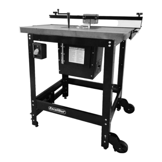
DELUXE ROUTER TABLE KIT
(Floor model)
MODEL
# 40-200C
© Copyright General® International
Advertisement
Table of Contents

Subscribe to Our Youtube Channel
Related Manuals for General Excalibur 40-200C

Summary of Contents for General Excalibur 40-200C
- Page 1 ROUTER INSERT PLATE 9 1/4” X 11 3/4” (235 X 298 MM) # 40-200C TABLE OPENING SIZES - DIAMETER PLATE: 3 3/4” (95 MM) INSERT RING: 1 1/2” (38 MM) NET WEIGHT (40-200C MODEL) 179 LBS (81 KG) © Copyright General® International...
- Page 2 THANK YOU for choosing this Excalibur by General International model ® 40-200 Deluxe Router Table Kit (floor model). This router table has been carefully tested and inspected before shipment and if properly used and maintained, will provide you with years of reliable service.
- Page 3 General ® International to have been directly or indirectly caused by or resulting from; improper use, or lack of or improper maintenance, misuse or abuse, negligence, accidents, damage in handling or trans- port, or normal wear and tear of any generally considered consumable parts or components.
-
Page 4: Table Of Contents
TABLE OF CONTENTS Rules for safe operation ......Operating instructions ........25-27 Before starting ............25 Placement within the shop / Using the spacer bars for jointing ......25 Establishing a safety zone ......Jointing ..............26 Groove cutting ............26 Safety ............ -
Page 5: Rules For Safe Operation
To help ensure safe operation, please take a moment to learn the machine’s applications and limita- tions, as well as potential hazards. GENERAL® INTERNATIONAL disclaims any real or implied war- ranty and holds itself harmless for any injury that may result from improper use of its equipment. -
Page 6: Placement Within The Shop / Establishing A Safety Zone
PLACEMENT WITHIN THE SHOP / ESTABLISHING A SAFETY ZONE THE MACHINE IS HEAVY (179 LBS - 81 KG). DO NOT OVEREXERT. ARRANGE TO HAVE HELP NEARBY AND READY FOR UNPACK- ING AND SET UP. SERIOUS PERSONAL INJURY COULD OCCUR IF YOU CONNECT THE MACHINE TO THE POWER SOURCE BEFORE YOU HAVE COM- PLETED THE INSTALLATION AND ASSEMBLY STEPS. -
Page 7: Identification Of Main Parts And Components
DELUXE ROUTER TABLE KIT (Floor model) MODEL #40-200C IDENTIFICATION OF MAIN PARTS AND COMPONENTS ON/OFF SWITCH WITH REMOVABLE SAFETY KEY DUST ENCLOSURE BOX ACCESS DOOR TABLE* AIR VENT FENCE RAIL WITH SLIDING SCALE ROUTER LIFT HANDLE HOLDER OUTFEED FENCE FACE STAND FENCE LOCKING HANDLE STAND CASTER PEDAL... -
Page 8: Unpacking
Carefully unpack and remove the components of the following 5 boxes - that make up a complete Excalibur Router Table - and check for damaged or missing items as per the list of contents below. NOTE: Please report any damaged or missing items to your General International distributor immediately. LIST OF CONTENTS... -
Page 9: List Of Contents - 40-125 Router Lift
Carefully unpack and remove the components of the following 5 boxes - that make up a complete Excalibur Router Table - and check for damaged or missing items as per the list of contents below. NOTE: Please report any damaged or missing items to your General International distributor immediately. LIST OF CONTENTS... -
Page 10: List Of Contents - Table
Carefully unpack and remove the components of the following 5 boxes - that make up a complete Excalibur Router Table - and check for damaged or missing items as per the list of contents below. NOTE: Please report any damaged or missing items to your General International distributor immediately. LIST OF CONTENTS 40-075 CAST-IRON TABLE (40-200C) * a- 24”... -
Page 11: 40-085 Router Table Stand
ASSEMBLY INSTRUCTIONS - 40-085 ROUTER TABLE STAND SERIOUS PERSONAL INJURY COULD OCCUR IF YOU CONNECT THE MACHINE TO THE POWER SOURCE BEFORE YOU HAVE COM- PLE-TED THE INSTALLATION AND ASSEMBLY STEPS. DO NOT CONNECT THE MACHINE TO THE POWER SOURCE UNTIL INSTRUCTED TO DO SO. - Page 12 the two sub assemblies using the front/rear bot- tom A and top B braces. Do not tighten the stand bolts until after you have fastened the stand to the router table top. (See step 3 on page 14.) The router lift crank handle may be stored on the holder as shown above.
-
Page 13: Assembly Instructions
ASSEMBLY INSTRUCTIONS - TABLE 40-075/40-049/40-045 SERIOUS PERSONAL INJURY COULD OCCUR IF YOU CONNECT THE MACHINE TO THE POWER SOURCE BEFORE YOU HAVE COM- PLE-TED THE INSTALLATION AND ASSEMBLY STEPS. DO NOT CONNECT THE MACHINE TO THE POWER SOURCE UNTIL INSTRUCTED TO DO SO. -
Page 14: Attach The Stand To The Table
ASSEMBLY INSTRUCTIONS - ATTACH THE STAND TO THE TABLE SERIOUS PERSONAL INJURY COULD OCCUR IF YOU CONNECT THE MACHINE TO THE POWER SOURCE BEFORE YOU HAVE COM- PLETED THE INSTALLATION AND ASSEMBLY STEPS. DO NOT CONNECT THE MACHINE TO THE POWER SOURCE UNTIL INSTRUCTED TO DO SO. -
Page 15: 40-080 Router Fence
ASSEMBLY INSTRUCTIONS - #40-080 ROUTER FENCE SERIOUS PERSONAL INJURY COULD OCCUR IF YOU CONNECT THE MACHINE TO THE POWER SOURCE BEFORE YOU HAVE COMPLETED THE INSTALLATION AND ASSEMBLY STEPS. DO NOT CONNECT THE MACHINE TO THE POWER SOURCE UNTIL INSTRUCTED TO DO SO. Before opening the fence, have a clear work area to prevent the mixing of hardware. - Page 16 6. Install the orange dust shield A on the two bolts and 5. Slide the 2 bolts and spacers to the middle of the secure in place using two flat washers B and 2 lock fence body (approx.) knobs C as shown in D. 7.
- Page 17 11. Insert a Phillips head screw A through both dust 13. Insert the square nut in the fence body slot, A. outlet mounting holes. 14. Insert the other square nut in the slot on the other 12. Loosely thread a square nut B on both screws as side of the fence, B.
-
Page 18: Prepare The Table For Router Lift
ASSEMBLY INSTRUCTIONS - PREPARE THE TABLE FOR ROUTER LIFT SERIOUS PERSONAL INJURY COULD OCCUR IF YOU CONNECT THE MACHINE TO THE POWER SOURCE BEFORE YOU HAVE COM- PLETED THE INSTALLATION AND ASSEMBLY STEPS. DO NOT CONNECT THE MACHINE TO THE POWER SOURCE UNTIL INSTRUCTED TO DO SO. -
Page 19: 40-130 Dust Collection Kit
ASSEMBLY INSTRUCTIONS - 40-130 DUST COLLECTION KIT SERIOUS PERSONAL INJURY COULD OCCUR IF YOU CONNECT THE MACHINE TO THE POWER SOURCE BEFORE YOU HAVE COM- PLETED THE INSTALLATION AND ASSEMBLY STEPS. DO NOT CONNECT THE MACHINE TO THE POWER SOURCE UNTIL INSTRUCTED TO DO SO. -
Page 20: Mounting A Router
All other motors (smaller diameters) will require a shim C (item # 40-626, available from you local General Intera- tional dealer), or a reducer collar such as our model 40-312 (for 3 1/2” motors) or 40-314 (for 3 1/4” motors), B, to center the router as well as prevent from overtightening the clamping system. - Page 21 Turn Allan cap screw A counter clockwise to Note: When mounting the Milwaukee model 5625/5626 motor, please ensure that a shim is between the router loosen clamp body B. The two threaded nuts C and the clamping surface of the lift. are there to help spread the clamp body.
-
Page 22: Leveling And Locking The Router Plate
LEVELING AND LOCKING THE ROUTER PLATE 4. The routers collet should now be protruding out from 1. Using a straightedge check that the router plate is the top plate. This will facilitate tool (router bit) level with the main table, A. changing from above the table eliminating the 2. -
Page 23: Basic Adjustments & Controls
BASIC ADJUSTMENTS & CONTROLS ADJUSTING THE FENCE ALONG THE RAILS The fence can be slid along the rails A. Loosen locking handles B, slide fence then lock in position by re-tightening the locking handle. Repeat on the other extremity of the fence. ADJUSTING THE SLIDING SCALE ON THE RAILS The scale on the rails can be adjusted along the rails A. -
Page 24: Connecting The Router To The Safety Switch
If you do not already own a dust collection system, con- sider contacting your General® International distributor for information on our complete line of dust collection systems or visit our website at: www.general.ca... -
Page 25: Operating Instructions
OPERATING INSTRUCTIONS MAKE SURE TO READ, UNDERSTAND, AND FOLLOW ALL OPERATING INSTRUCTIONS AND SAFETY GUIDELINES THAT CAME WITH YOUR ROUTER – FAILURE TO DO SO MAY LEAD TO SERIOUS INJURY AND/OR DAMAGE TO THE ROUTER, ROUTER TABLE, OR WORKPIECE. BEFORE STARTING: •... -
Page 26: Jointing
JOINTING 1. Loosen but do not remove the outfeed fence face and install the spacer bars between the outfeed fence and the fence body. 2. With the router unplugged and the safety switch in the off position, follow the instructions supplied with your router and install a straight cutting bit in the router. -
Page 27: Profile Cutting
PROFILE CUTTING Profile cutting is usually performed using a bit with a guide bearing. The guide bearing controls the depth of cut into the edge face of a board. A good example would be a chamfer bit A. The bearing rides along the uncut edge of the board while the cutter removes the wood. -
Page 28: Recommended Optional Accessories
RECOMMENDED OPTIONAL ACCESSORIES We offer some optional accessories available from your local General International dealer for increased con- venience, productivity, accuracy and safety when using your router table. For more information about our products, please visit our website at www.general.ca... - Page 29 Notes...
-
Page 30: Parts List & Diagrams
Cast-iron table (with model #40-200C) PARTS LIST – #40-075 PART NO. REFERENCE NO. DESCRIPTION SPECIFICATION 40075-01 3224U014 CAST-IRON TABLE 32” X 24” 40075-02 903M06030 FLAT HEAD CAP SCREW M6 X 30 MM 40075-03 910M06000 HEX NUT 40075-04 905M06020 FLAT HEAD SCREW M6 X 20 MM 40075-05 914M061602... - Page 31 MDF table (with model #40-200M) PARTS LIST – #40-049 PART NO. REFERENCE NO. DESCRIPTION SPECIFICATION 40049-01 3224E014B MDF TABLE (3224) 800 X 600 40049-02 903M06030 FLAT HEX SOCKET HEAD SCREW M6 X 30 40049-03 907M06013 WOOD NUT M6 X 13 40049-04 907007004 WOOD SCREW...
- Page 32 Router Fence (#40-080) 6 17 PARTS LIST – #40-080 PART NO. REF. N0. DESCRIPTION SPECIFICATIONS 40080-01 32240032A FENCE BODY 910MM 40080-02 60100001A LOCK HANDLE 5/16” 40080-03 T3224002 SCALE 910MM 40080-04 32240052A T-BOLT 40080-05 9145162302 FLAT WASHER 40080-06 939M08000B LOCK KNOB 40080-07 32240034 LOCK NUT...
- Page 33 Stand (#40-085)
- Page 34 PARTS LIST – #40-085 PART N0. REF. NO. DESCRIPTION SPECIFICATIONS NOTES:...
- Page 35 Router lift (#40-125)
- Page 36 PARTS LIST – #40-125 PART NO. REF. N0. DESCRIPTION SPECIFICATIONS 0125-01 60800001A ALUMINUM CARRIAGE BRACKET 40125-02 60500002 MAIN GEAR SHAFT 40125-03 60500003 LEAD SCREW 40125-04 60100017 INSERT RING 1-1/2” 40125-05 60500005 GEAR SHAFT 40125-06 60800021 CARRIAGE PLATE 40125-07 60800004 CLAMP POST 40125-08 60800007A TOP PLATE...
- Page 37 Dust Collection Kit (#40-130) PARTS LIST – #40-130 PART NO. REF. NO. DESCRIPTION SPECIFICATIONS 40130-01 32240001 FRONT BOX PANEL 40130-02 32240002 RIGHT BOX PANEL 40130-03 PHILLIPS HEAD SCREW 40130-04 PHILLIPS HEAD SCREW 40130-05 32240003 HINGE 40130-06 32240004 LEFT BOX PANEL 40130-07 32240005 REAR BOX PANEL...
-
Page 38: Contact Information
MODEL 40-200C IMPORTANT When ordering replacement parts, always give the model number, serial number of the machine and part number. Also a brief description of each item and quantity desired.
Need help?
Do you have a question about the Excalibur 40-200C and is the answer not in the manual?
Questions and answers