
Subscribe to Our Youtube Channel
Related Manuals for ELTRA ELEMENTRAC ONHp2


Summary of Contents for ELTRA ELEMENTRAC ONHp2
- Page 1 Operating instructions ELEMENTRAC ONHp2 Translation © Eltra GmbH, Germany, 42781 Haan, Retsch-Allee 1-5, Germany | 06.10.2021 Version 0005...
- Page 2 Table of contents Copyright © Copyright by Eltra GmbH Retsch-Allee 1-5 42781 Haan Germany...
- Page 3 Table of contents...
-
Page 4: Table Of Contents
Table of contents Table of contents Table of contents ............................. 4 Additional operating instructions ......................6 Explanations of signs and symbols ....................6 Disclaimer ............................6 Copyright ............................6 Safety ..............................7 Explanations of the safety instructions ....................8 General safety instructions ........................ 9 Repairs ............................. - Page 5 Table of contents 10.5.1 Overview of the reagent tubes ....................62 10.5.2 Fill the reagent tube of the catalyst ..................63 10.5.3 Fill the reagent tube of the gas processing (thermal conductivity cell, carrier gas) ....64 10.5.4 Fill the dust trap of the reagent tube ..................65 10.5.5 Filling the reagent tube of the water trap .................
-
Page 6: Additional Operating Instructions
1.3 Copyright These operating instructions or parts thereof may not be reproduced, distributed, edited or copied in any form without prior written permission of Eltra GmbH. Any violation may result in claims for damages. -
Page 7: Safety
All persons who operate, clean, work with or on the device. This device is a modern, high-performance product of the Eltra GmbH and was developed according to the latest state of the art. Operational safety is ensured if this device is used in accordance with its intended purpose and if the operating instructions provided here are followed. -
Page 8: Explanations Of The Safety Instructions
Safety 2.1 Explanations of the safety instructions The following warnings in this operating instructions indicate potential hazards and damages: DANGER D1.0000 Risk of fatal injuries Source of danger − Possible consequences if the danger is ignored. • Instructions and advices on how to avoid the hazard. Failure to observe the warning “Danger”... -
Page 9: General Safety Instructions
N2.0012 Changes to the device Improper modifications − The conformity to the European directives declared by Eltra GmbH shall lose its validity through improper modification. Any warranty claims shall become void. • Do not make any unauthorised modifications to the device. -
Page 10: Repairs
2.3 Repairs This operating instructions do not include any repair instructions. For safety reasons, repairs may only be carried out by Eltra GmbH or an authorised representative as well as by qualified service technicians. In case of any repair, please contact…... -
Page 11: Safety Symbols On The Device
Safety 2.6 Safety symbols on the device Safety symbols on the ONH-p 2 device warn of potential hazards when operating the device. The following safety symbols can be found on the analyser: Figure 1: Safety symbols on the analyser... -
Page 12: Emergency Stop
Safety Position Component Description The warning symbols 1: in the rear area of the cover plate 3: in the upper, central area of the right side wall 1,3,6 6: On the door at the rear side of the device there is a warning symbol attached which means that these covers may only be opened by qualified personnel. - Page 13 Safety WARNING W3.0002 Danger to life from electric shock Damaged power cable − Operating the device with a damaged power cable or plug can lead to life- threatening injuries from electric shock. • Before operating the device, check the power cable and plug for any damage.
- Page 14 Safety WARNING W6.0000 Danger of poisoning Toxic combustion gases − The samples are exposed to high temperatures during analysis. In this process, harmful gaseous fission products can be released or formed from reaction processes. These gases can escape from the gas outlet or the furnace and cause severe poisoning.
- Page 15 Safety CAUTION C4.0000 Risk of injury Moving parts − The furnace closes after user input. Hands in the area of the opening can be crushed when the furnace closes. • Never reach into the oven when it is closing. • Use crucible tongs in order to place crucibles. CAUTION C5.0000 Risk of injury...
- Page 16 Safety CAUTION C9.0000 Risk of burns Hot equipment parts − Parts of the device can become very hot and cause burns during the performance of any maintenance work if the waiting time for cooling is not observed. • Please wait until the furnace temperatures cooled down to < 40 before performing any maintenance work.
- Page 17 Safety CAUTION C13.0000 Risk of injury Pressurised system − The device is pressurised during operation. Removing reagent tubes during operation may lead to an explosive escape of chemicals or sample material and can cause injuries. • Never remove any reagent tubes during operation. •...
-
Page 18: Description
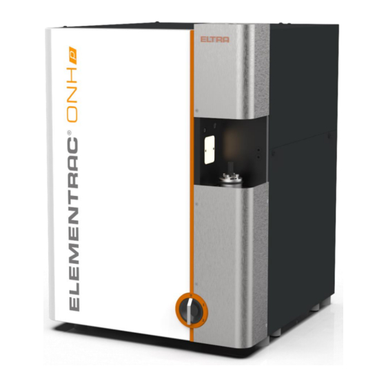
The gaseous combustion products are measured by infrared and thermal conductivity cells. 3.1 Analyser ONH-p 2 3.1.1 Front side The following figure shows the front side of the device: Figure 2: Front side of the ELEMENTRAC ONHp2... - Page 19 Description Position Component Description Catalyst furnace Is used for the processing of analysis gases Reagents Are used for the processing of analysis gases Sample receipt This is where the sample to be analysed is inserted. Furnace cover The impulse furnace is located behind the cover. Dust filter This filter removes particles from the gas flow.
-
Page 20: Rear Side Of The Analyser
Description 3.1.2 Rear side of the analyser The following figure shows the rear side of the analyser: Fig. 1: side of the analyser... - Page 21 The USB port is used for the communication with the USB port Supply connection of the heat This is where the power supply for the Eltra heat exchanger exchanger is connected. This is where the compressed air supply for the Connection of the compressed air pneumatics is connected.
-
Page 22: Auto Cleaner
Description 3.1.3 Auto cleaner Fig 2: Auto cleaner Position Component Description Housing of the auto cleaner with integrated dust Auto cleaner extraction. Brush Cleaning brush of the auto cleaner. Ensures that the dust produced during cleaning is not distributed throughout the room. The dust is Dust catcher vacuumed up in the housing of the auto cleaner at the end of the cleaning process. -
Page 23: Installation
Installation 4 Installation 4.1 Transport and unpacking WARNING W9.0000 Risk of life-threatening injuries Falling loads − The device may only be transported or lifted with suitable aids, such forklift or crane. Loads can fall down and cause life-threatening injuries. • Lift and transport the device exclusively by means of suitable aids, such as forklift or crane. - Page 24 Installation The analyser is delivered in a solid cardboard box. The analyser itself is placed on a wooden pallet. The delivery includes 2 round slings which shall be used to lift the analyser out of the box. • Open the cardboard box at the top. •...
-
Page 25: Setting Up
• Please ensure that all feet of the device have a secure footing. The space which is required to set up the device ELEMENTRAC ONHp2 ONH-p 2 with scale and PC is approx. 190 cm × 75 cm (width × depth) and approx. 100 cm × 75 cm without scale and PC. - Page 26 Installation The device is set up as follows: 1. Place the device at the prepared location. 2. Please make sure that you position the device in such a way that the fans are not blocked. 3. Set up the PC, monitor, keyboard and scales in the desired location in such a way that the analyser can be easily seen.
-
Page 27: Filling The Reagent Tubes
Installation 4.3 Filling the reagent tubes WARNING W11.0017 Risk of injury Hazardous chemicals − When working on the device, hazardous chemicals can cause fatal poisoning or severe skin burns • Please observe the safety data sheet in terms of the substances used. •... - Page 28 Installation In order to fill the individual reagents properly, please see Section 10.5 Filling of reagent tubes...
-
Page 29: Providing The Gas Supply
Installation 4.4 Providing the gas supply CAUTION C22.0000 Risk of injury Pressurised system − The device is pressurised during operation. Removing reagent tubes during operation may lead to an explosive escape of chemicals or sample material and can cause injuries. •... -
Page 30: The Cooling Water Supply Is Provided
Installation 4.5 The cooling water supply is provided The analyser must be cooled with water during operation. When establishing the water supply for the device, please observe the relevant instructions on the water connections of the device. The directions of the water flow are clearly marked there. There are two options for the cooling: 1. -
Page 31: Connection Of A Third-Party Heat Exchanger
Installation b. Connect the water inlet of the analyser to connection 2 of the heat exchanger. 6. Connect the heat exchanger to the operator's water supply: a. Connect the inflow of the water supply to connection 3 of the heat exchanger. b. - Page 32 Installation b. Connect the water inlet of the analyser to the corresponding connection of the heat exchanger. 3. Check all water connections for any leaks.
-
Page 33: Connect The Device To The Pc
Installation 4.6 Connect the device to the PC The connection of the device to the PC is carried out as follows: 1. Connect the USB port on the analyser (please see „Rear side of the analyser “) to the corresponding interface on the PC. Use the supplied cable. The device is now connected to the PC. -
Page 34: Installing The Auto Cleaner (Optional)
Installation 4.8 Installing the auto cleaner (optional) The following conditions must be met before installing the auto cleaner: • The device is set up; see “Setting up“. • The reagent tubes are filled; see “Filling reagent tube”. • The device is connected to the PC; see “Connecting device with PC”. •... - Page 35 Installation 4. Assemble the cable clip and secure it with an M20+ U washer. 5. Remove the compressed air line P4 from the valve unit. 6. Assemble the auto cleaner and secure it initially only with the top screw M6x20. 7.
- Page 36 Installation 8. Secure the auto cleaner with the lower screw M6x20 and tighten both screws. 9. Disconnect the 24VDC, oven sensor and CAN bus line in the analyser and let it hang down to the side outside the device. 10. Take the control assembly of the auto cleaner and connect the compressed air line P4 with the control assembly.
- Page 37 Installation 21. Push the auto cleaner up into the oven and hold it there. 22. Carefully retighten the two previously loosened screws completely. 23. Release the auto cleaner. 24. Connect the two compressed air lines of the auto cleaner to the control assembly (blue to blue, black to black).
-
Page 38: Commissioning
Commissioning 5 Commissioning 5.1 Commissioning and setting up the ELEMENTRAC ONH-p 2 CAUTION C23.0000 Risk of injury Pressurised system − The device is pressurised during operation. Removing the reagent tube during operation leads to the explosive escape of chemicals or sample material and may cause injuries. - Page 39 Commissioning Put the device into operation as follows: 1. Switch on the PC and start the ELEMENTS software. 2. Switch on the carrier gas. 3. Switch on the compressed air supply. 4. Turn the main switch to position 1; see “Front panel”. 5.
- Page 40 Commissioning 15. Select an application and work through the application-specific paramaters for the auto cleaner. You can set the frequency of automatic cleaning in the application parameters (cleaning interval): 1 =after every analysis; 10 = after every 10th analysis. 16. You can similarly set the cleaning duration in seconds. 17.
-
Page 41: Operation Of The Device
Operation of the device 6 Operation of the device WARNING W14.0021 Fire hazard / Risk of burns Hot parts (crucibles, reagents,...) can fall down − Ignition of tables, floors or any other surface on which the hot parts can fall. −... - Page 42 Operation of the device CAUTION C24.0000 Risk of injury Moving parts − The furnace closes after user input. Hands in the area of the opening can be crushed when the furnace closes. • Never reach into the oven when it is closing. •...
- Page 43 Operation of the device In order to perform any analyses, please carry out the following: 1. Please make sure that the PC is switched on and the ELEMENTS software has been started (please see „Commissioning“). 2. Please make sure that the main switch of the analyser has been turned to position 2 and that the device is heated up.
-
Page 44: Technical Data
Technical data 7 Technical data 7.1 Technical data ELEMENTRAC ONH-p 2 The following table lists the technical data for the device in 3-phase configuration: Definition Description Value Width 56 cm Depth 64 cm Dimensions and weight Height 78 cm Weight approx. - Page 45 Technical data Definition Description Value Connection Polyamide hose 6/4 mm (adapter with G¼" internal thread, included in the scope of delivery) Compressed air Type Water and oil free Pressure 4 to 6 bar (60 to 90 psi) Connection Polyamide hose 4/2 mm (adapter with G¼" internal thread, included in the scope of delivery) Volume...
-
Page 46: Name Plate Elementrac Onh-P 2
Technical data 7.2 Name plate ELEMENTRAC ONH-p 2 The following figure shows an example of the nameplate on the device: Figure 3: Name plate Position Component Manufacturer address Item number Mains frequency Protection class Read the operating instructions CE label Disposal label Current Voltage... -
Page 47: List Of Standards
Technical data 7.3 List of standards The following standards for inorganic materials are observed: Standard Elements Materials Devices ON-p Steel, iron, ASTM E 1019:2018 N, O OH-p nickel/cobalt alloys ONH-p ON-p Titanium and ASTM E 1409:2013 N, O OH-p titanium alloys ONH-p Titanium and OH-p... -
Page 48: Troubleshooting On The Elementrac Onh-P 2
• The use of organic solvents to clean the housing is not permitted. The outside of the device ELEMENTRAC ONHp2 must be cleaned on a regular basis. In order to clean the outside of the device, please proceed as follows: 1. -
Page 49: Cleaning The Dust Trap
Cleaning 9.2 Cleaning the dust trap CAUTION C27.0000 Cutting injuries Broken glass − Sample tubes and reagent tubes are made of glass and can break. Broken glass can cause cutting injuries. • Please check reagent tubes and sample tubes for any damage before use. -
Page 50: Cleaning The Furnace Area
• Never reach into the oven when it is closing. • Use crucible tongs in order to place crucibles. The outside of the furnace area of the ELEMENTRAC ONHp2 must be cleaned on a regular basis in order to ensure that reliable and reproducible measurement results can be achieved. -
Page 51: Maintenance
Maintenance 10 Maintenance 10.1 Overview of the maintenance work The following maintenance instructions refer to standard steel analyses with the ONH-p 2 for 25 to 50 samples per day and 99.995% pure carrier gas. Depending on the application, the maintenance cycle must be intensified in order to maintain the precision of the analysis results. The following table lists the maintenance work to be carried out. - Page 52 Maintenance – After 50 analyses or at least 2 times a day • „Furnace Clean furnace and electrodes. Further information can be found in Section cleaning“. – After 500 analyses • Replace all chemicals (except copper oxide). Further information can be found in Section „Removing and installing of reagent tubes“...
-
Page 53: Removing And Installing Of Reagent Tubes
Maintenance 10.2 Removing and installing of reagent tubes WARNING W17.0017 Risk of injury Hazardous chemicals − When working on the device, hazardous chemicals can cause fatal poisoning or severe skin burns • Please observe the safety data sheet in terms of the substances used. •... - Page 54 Maintenance CAUTION C33.0090 Risk for eye injuries Chemicals − When chemicals are replaced, small particles of the chemicals can float in the air and burn the eyes. • Please always wear protective goggles when working with chemicals. • Please observe the safety data sheets in terms of the chemicals used.
- Page 55 Maintenance Figure 4: Remove the reagent tube on the front side of the analyser. In order to insert the reagent tubes on the front side of the analyser, please proceed as follows: 1. Please make sure that the main switch of the analyser is set to switch position 1. 2.
- Page 56 Maintenance The following figure shows an example of how to insert a reagent tube on the front side of the analyser: Fig. 6: Inserting a reagent tube on the front side of the analyser 6. Hold the filled reagent tube (3) at a slight angle. 7.
-
Page 57: Reagents
Maintenance 10.3 Reagents The fillings of the reagent tubes are replaced when they are saturated. The following chemicals are used: as a moisture absorbent Magnesium perchlorate (anhydrone) Sodium hydroxide as CO absorbent as oxidant (CO → CO Copper oxide, contactors reagent NOTICE Set up a “counter”... -
Page 58: Replacing The Reagent Tube Of The Catalyst Furnace
Maintenance 10.4 Replacing the reagent tube of the catalyst furnace WARNING W18.0017 Risk of injury Hazardous chemicals − When working on the device, hazardous chemicals can cause fatal poisoning or severe skin burns • Please observe the safety data sheet in terms of the substances used. - Page 59 Maintenance CAUTION C37.0000 Cutting injuries Broken glass − Sample tubes and reagent tubes are made of glass and can break. Broken glass can cause cutting injuries. • Please check reagent tubes and sample tubes for any damage before use. • Please wear protective gloves and goggles when handling with reagent tubes and sample tubes.
- Page 60 Maintenance • Carefully pull the gas connection upwards with a slight rotating motion and let it hang down to the side. Gas connection • Carefully pull the reagent tube upwards with a slight rotating motion. • Replace the copper oxide as described in Section 10.5.2. •...
-
Page 61: Filling Of Reagent Tubes
Maintenance 10.5 Filling of reagent tubes WARNING W19.0017 Risk of injury Hazardous chemicals − When working on the device, hazardous chemicals can cause fatal poisoning or severe skin burns • Please observe the safety data sheet in terms of the substances used. •... -
Page 62: Overview Of The Reagent Tubes
Maintenance 10.5.1 Overview of the reagent tubes Figure 5: Front side of the analyser with the device door open Position Component Dust trap, sinter filter Water trap after the catalyst furnace, anhydrone CO converter, contactors reagent Gas processing for the carrier gas, anhydrone / sodium hydroxide Gas processing for the thermal conductivity cell, anhydrone / sodium hydroxide Catalyst, copper oxide... -
Page 63: Fill The Reagent Tube Of The Catalyst
Maintenance 10.5.2 Fill the reagent tube of the catalyst In order to replace the filling of the catalyst (see Section (1) in „10.5 Filling of reagent tubes“) and proceed as follows: 90330 1,5-2cm 1. Turn the main switch of the analyser to switch position 1. -
Page 64: Fill The Reagent Tube Of The Gas Processing (Thermal Conductivity Cell, Carrier Gas)
Maintenance 10.5.3 Fill the reagent tube of the gas processing (thermal conductivity cell, carrier gas) Before replacing the filling of the gas processing, please see items (2 and 3) in Fehler! Verweisquelle konnte n icht gefunden werden.) and proceed as follows: 90331 1,5-2cm 1. -
Page 65: Fill The Dust Trap Of The Reagent Tube
Maintenance 10.5.4 Fill the dust trap of the reagent tube Before replacing the filling of the dust trap, please see Section (4) in „10.5 Filling of reagent tubes“) and proceed as follows: 1. Turn the main switch of the analyser to switch position 1. 2. -
Page 66: Filling The Reagent Tube Of The Water Trap
Maintenance 10.5.5 Filling the reagent tube of the water trap In order to replace the filling of the catalyst (see Section. (5) in „10.5 Filling of reagent tubes“) and proceed as follows: 90331 1,5-2cm 1. Turn the main switch of the analyser to switch position 1. -
Page 67: Filling The Reagent Tube Of The Co Converter
Maintenance 10.5.6 Filling the reagent tube of the CO converter In order to replace the filling of the catalyst (see Section (6) in „10.5 Filling of reagent tubes“) and proceed as follows: 90331 1,5-2cm 1. Turn the main switch of the analyser to switch position 1. -
Page 68: Maintenance In The Furnace Area
Maintenance 10.7 Maintenance in the furnace area 10.7.1 Changing the seal of the upper furnace closure CAUTION C41.0000 Risk of injury Moving parts − The lock moves according to user input. Hands in the area of the upper furnace lock can be crushed when the lock closes. •... - Page 69 Maintenance • Remove the old O-ring and clean the surfaces. • Insert the new O-ring free of grease. • Reinstall the furnace lock assembly. Please make sure that the locking element engages into the guiding element of the pneumatic cylinder. •...
-
Page 70: Changing The Seal Of The Lower Furnace Lock
Maintenance 10.7.2 Changing the seal of the lower furnace lock CAUTION C42.0000 Risk of injury Moving parts − The furnace closes after user input. Hands in the area of the opening can be crushed when the furnace closes. • Never reach into the oven when it is closing. •... -
Page 71: Replacing The Upper Electrode
Maintenance 10.7.3 Replacing the upper electrode CAUTION C43.0000 Risk of injury Moving parts − The lock moves according to user input. Hands in the area of the upper furnace lock can be crushed when the lock closes. • Never reach into a moving lock. CAUTION C44.0000 Risk of injury... - Page 72 Maintenance NOTICE Do not use a Torx® screwdriver with a ball head. The screws may be very tight and the ball head could thereby tear off and damage the screw. • Remove the electrode of the furnace from below. • Clean the inside of the furnace with a dry cloth.
-
Page 73: Complete Electrode Replacement, Including Screws
Maintenance • Reinstall the furnace lock assembly. Please make sure that the locking element engages into the guiding element of the pneumatic cylinder • Insert the two nuts and tighten them. • Put the upper furnace cover on from above and fasten it with the screw. •... - Page 74 Maintenance • Loosen the four fastening screws of the upper part of the furnace and carefully remove the furnace part. • Remove the compressed air hoses from the two vertical pneumatic cylinders. • Loosen the three screws which hold the electrode in place. Use the supplied Torx® screwdriver for this purpose.
- Page 75 Maintenance • Clean the seat of the flat seal. • Clean the inside of the oven with a dry cloth. • Insert the new electrode into the furnace from the bottom up. The electrode has a coding to enable a better orientation. This must point to the right. •...
-
Page 76: Replace Lower Electrode (Graphite Tip)
Maintenance • Reinstall the furnace lock assembly. Please make sure that the locking element engages into the guiding element of the pneumatic cylinder. • Insert the two nuts and tighten them. • Put the upper furnace cover on from above and fasten it with the screw. •... -
Page 77: Replacing The Brush Of The Auto Cleaner
Maintenance • Check the fitting for any possible damages and replace it, if necessary. • Insert the new lower electrode (graphite tip) into the fitting. • Secure the fitting and the lower electrode with the 4 screws. • Turn the main switch of the analyser to position 2. The lower electrode (graphite tip) has been replaced. -
Page 78: Spare Parts
Spare parts 11 Spare parts 11.1 Spare parts Analyser 11.1.1 Front side of the device Fig. 7: Figure: The front side is closed Position Name Item number Quantity Hinge with eccentric pin 88400-0288... -
Page 79: Front Side (Interior View)
Spare parts 11.1.2 Front side (Interior view) Fig. 8: Figure: Interior view of the front side... - Page 80 Spare parts Position Name Item number Quantity Filter connection bracket, dust filter 11045 O-ring 9x3 70230 Sinter filter with O-ring 27000-2040 Reagent tube dust filter 11064-3001 Upper reagent tube holder 11042 Reagent tube 88400-0006 Lower reagent tube holder 11045 Oval-head screw M6x10 08.401.0050 Catalyst furnace cover 20100-3205...
-
Page 81: Lower Furnace
Spare parts 11.1.3 Lower furnace Quantity Position Name Item number Lower electrode, 31360 graphite tip Lower electrode 31365-8000 holder with screws O-ring 47,2x5,7 70405 High vacuum 92610 grease Countersunk screw 08.643.0185 M3x12 Lower furnace 27000-3220 cover Pneumatic cylinder 66200-0184 furnace Furnace, Front view Fig. -
Page 82: Upper Furnace
Spare parts 11.1.4 Upper furnace Fig. 10: Furnace cleaning mechanism Position Name Item number Quantity Locking nut M5 08.642.0053 O-ring 15x3,5 66200-0212 Seal kit of upper furnace not illustrated 27000-8007 (contains all relevant seals) Sample lock drive 27000-2089 Upper electrode, complete 27000-8006 (including screws and seals) -
Page 83: Rear Side Of The Device
Spare parts 11.1.5 Rear side of the device Fig. 11: Rear side Name Item number Quantity Position Fan 24V 66027-6225 Socket outlet SCHUKO 88400-0413 Circuit breaker 1P 10A 66400-0627 Circuit breaker 2P 32A 77033 @ 3-phase device Circuit breaker 2P 63A 77034 @ 1-phase device... -
Page 84: Left Side Of The Device
Spare parts 11.1.6 Left side of the device CAUTION C46.0000 Risk of injury Moving parts − There are fans inside the left side of the analyser. Spinning fans can cause injuries to fingers. • Never reach into a rotating fan. Fig. -
Page 85: Left Side, Devgate
Spare parts 11.1.6.1 Left side, DevGate Fig. 13: DevGate Name Item number Quantity Position Fan 24VDC 66027-6225 Circuit board DevGate 88600-5100... -
Page 86: Left Side, Inlet Valves
Spare parts 11.1.6.2 Left side, inlet valves Name Item number Quantity Position Circuit board pressure sensor 11492 Switch valve 25196 Valve block gas inlet, 27000-2018 complete... -
Page 87: Valve Block, Compressed Air Control
Spare parts 11.1.6.3 Valve block, compressed air control Valve block, compressed air control Fig. 14: 27000-2024 Quantity Name Item number Valve, 5/2-ways 66200-0140 Valve, 5/3-ways 66200-0139 Pressure regulator 60236 Pressure switch 66300-0158 Valve, 2/2-ways 66200-0141... -
Page 88: Right Side Of The Device
Spare parts 11.1.7 Right side of the device Fig. 15: Right side Name Item number Quantity Position Water flow sensor 66027-6024 Valve block upper furnace, 66200-3333 complete... -
Page 89: Upper Mounting Plate
Spare parts 11.1.8 Upper mounting plate DANGER D3.0005 Danger to life from electric shock Exposed electrical contacts – High voltage − An electric shock can cause severe injuries in the form of burns, cardiac arrhythmias, respiratory arrest or cardiac arrest. •... - Page 90 Spare parts Position Name Item number Quantity 27000-5007 Circuit board voltage sensor 27000-5002 Circuit board current sensor 66300-0477 Power supply 27000-5001 Circuit board catalyst furnace 66400-0061 Toroidal transformer catalyst furnace 88400-0394 Power controller Maxthermo...
-
Page 91: Auto Cleaner Spare Parts
Spare parts 11.2 Auto cleaner spare parts Fig. 18: Auto cleaner Position Article number Quantity Name Adapter for vacuum cleaner 27100-3609 Brush 27100-4999 Dust trap complete 27100-8001 O ring 60x4 05.114.0004 Fig. 17: Control assembly for auto cleaner... - Page 92 Spare parts Article Position Quantity Name number 27100- Autoloader Child 5001 27100- Valve assembly 2042 27000- Manomer 5019 27100- Pressure reducer 5021...
-
Page 93: Fuses
Spare parts 11.3 Fuses Quantity Item number Name Fuse T8A 66300-0376 for 27000-5100 DevGate 2 Circuit board Fuse 3.15A 66300-0410 for upper mounting plate T5A IO circuit board, pump cable 66300-0372 and IRC board cable T6.3A 27000-5001 PCB furnace 66300-0369 power controller T4A Catalyst furnace fuse 66400-0681... -
Page 94: Decommissioning
Decommissioning 12 Decommissioning The device can be taken out of operation as follows: 1. Please ensure that the device is turned off and cooled down. 2. Unplug the analyser from the mains. 3. Please make sure that the gas supply of the carrier gas is switched off. 4. -
Page 95: Disposal
Disposal 14 Disposal In the event of disposal, the respective statutory regulations must be observed. Information on the disposal of electrical and electronic devices within the European Community is listed below. Within the European Community, disposal of electrically operated devices is specified by national regulations which are based on the EU Directive 2012/19/EU on waste electrical and electronic equipment (WEEE). - Page 96 Copyright © Copyright by Eltra GmbH Retsch-Allee 1-5 42781 Haan Germany...
Need help?
Do you have a question about the ELEMENTRAC ONHp2 and is the answer not in the manual?
Questions and answers