Advertisement
Quick Links
©2009 ClearSpan™
All Rights Reserved. Reproduction is prohibited
without permission.
Revision date: 07.23.09
ClearSpan
Job Master Shop Buildings
™
Photo may show a different but similar model.
CLEARSPAN
24' Wide
JOB MASTER BUILDINGS
™
STK#
DIMENSIONS
106777
24' W x 20' L
106778
24' W x 24' L
106779
24' W x 28' L
106780
24' W x 32' L
106781
24' W x 36' L
106782
24' W x 40' L
106783
24' W x 44' L
1
Advertisement

Subscribe to Our Youtube Channel
Related Manuals for ClearSpan 106777


Summary of Contents for ClearSpan 106777
- Page 1 ClearSpan Job Master Shop Buildings ™ 24' Wide Photo may show a different but similar model. STK# DIMENSIONS 106777 24' W x 20' L 106778 24' W x 24' L 106779 24' W x 28' L 106780 24' W x 32' L...
-
Page 2: Safety Precautions
• Never erect the structure under power lines. • Identify whether underground cables and pipes are Thank you for purchasing this ClearSpan™ shelter. When present before preparing the site or anchoring the properly assembled and maintained, this product will structure. -
Page 3: Assembly Procedure
These words and phrases are common to most ends of a pipe can be inserted into couplers and the ClearSpan™ shelters and identify the different parts of the straight ends of other pipes. shelter. (Some are used in this document. Others may not •... -
Page 4: Required Tools
CLEARSPAN JOB MASTER BUILDINGS ™ REQUIRED TOOLS Space below is reserved for customer notes. The following list identifies the main tools needed to assemble the shelter. Additional tools and supports may be needed depending on the structure, location, and application. - Page 5 CLEARSPAN JOB MASTER BUILDINGS ™ The following graphics and photos will help you identify the different parts and show you how they are used. (Some parts are not shown.) FA4482B 100441 102921B Tek Screw Nut Setter Neo-bonded Galvanized Washer 104075...
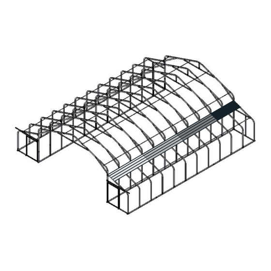
- Page 6 CLEARSPAN JOB MASTER BUILDINGS ™ ClearSpan® Job Master Shop Building (24' Wide) with Outriggers OVERVIEW This section is an overview of the process for assembling your building. See illustration below to identify the main parts of your Job Master Shop Building.
- Page 7 CLEARSPAN JOB MASTER BUILDINGS ™ LAY OUT THE BUILDING SITE The base rails consist of 2" x 3" square tubing (plain and swaged) and run the length of the building. After the site is prepared, determine where the building will...
-
Page 8: Rafter Assembly
CLEARSPAN JOB MASTER BUILDINGS ™ 5. Position base rails on the site where the shelter will be ASSEMBLE AND POSITION MAIN FRAME BASE RAILS assembled. (CONTINUED) ATTACH 105188 1-WAY CONNECTOR (RAFTER FEET) 6. Space rails at the approximate width of the shelter. - Page 9 CLEARSPAN JOB MASTER BUILDINGS ™ MAIN FRAME RAFTER ASSEMBLY 3. Locate four (4) pipe straps (#QH1070) and attach each strap to the rafter assembly on the underside of the Gather the parts: rafter at each tube joint as shown. •...
- Page 10 CLEARSPAN JOB MASTER BUILDINGS ™ MAIN FRAME RAFTER ASSEMBLY (CONTINUED) 7. Select the two (2) 64" plain tubes (#S20P064) and connect them using the 16" plain tube insert (#104075) 5. Once the rafter tubes for the first rafter are assembled and Tek screws.
- Page 11 CLEARSPAN JOB MASTER BUILDINGS ™ MAIN FRAME RAFTER ASSEMBLY (CONTINUED) 13. After attaching the first two connection plates, flip the rafter assembly over and attach the remaining two (2) The below diagram shows the assembled center connection plates for the rafter.
-
Page 12: Main Frame Assembly
CLEARSPAN JOB MASTER BUILDINGS ™ MAIN FRAME ASSEMBLY 4. From the location marked in the previous step, The following instructions assume the rafter feet (105088) measure forty-eight inches (48") and make another are properly spaced on the base rails as previously mark. - Page 13 CLEARSPAN JOB MASTER BUILDINGS ™ MAIN FRAME ASSEMBLY (CONTINUED) 15. Verify that the distance between the rafters is 48" center-to-center at the top. Adjust the rafter forward or 7. Rotate the purlin pipe so that the first mark is visible backward as needed to maintain this dimension.
- Page 14 CLEARSPAN JOB MASTER BUILDINGS ™ SQUARE THE ASSEMBLED MAIN FRAME The diagrams below illustrate two possible ways to properly anchor the shelter to the site. Complete these steps: 1. Perform a final square of the main frame by measuring diagonally (corner-to-corner) at the base and verify that the two measurements are equal.
- Page 15 CLEARSPAN JOB MASTER BUILDINGS ™ ASSEMBLE OUTRIGGER RAFTERS 3. After connecting the separate pipes, locate one (1) pipe strap (#QH1070) and install as shown. Each outrigger rafter consists of two (2) large 2" x 3" rectangular pipes and a pipe strap.
- Page 16 CLEARSPAN JOB MASTER BUILDINGS ™ ATTACH 105088 1-WAY CONNECTOR (RAFTER FEET) ASSEMBLE OUTRIGGER BASE RAILS This procedure describes one way to assemble the Gather the parts: outrigger base rail and to attach the heavy-duty 1-Way • Assembled base rails connectors, used to secure the rafter legs, to the base rail.
- Page 17 CLEARSPAN JOB MASTER BUILDINGS ™ 4. With the first rafter secured to the outrigger base rail, OUTRIGGER FRAME ASSEMBLY realign the base rail and rafter with those of the main frame as needed and locate two (2) connection plates At this point, all outrigger rafters are assembled and all (#105087).
- Page 18 CLEARSPAN JOB MASTER BUILDINGS ™ OUTRIGGER FRAME ASSEMBLY (CONTINUED) NOTE: End the purlin run with the shorter, plain pipe (131P0XX), where the XX represents the length 9. Secure the second rafter to the 1-Way connector on needed to reach the end of the frame. This pipe does the outrigger base rail and adjust the rafter width as not have a swaged/tapered end.
- Page 19 CLEARSPAN JOB MASTER BUILDINGS ™ INSTALL MAIN FRAME BRACING READ THE MUST READ DOCUMENT TO PROPERLY ANCHOR THE SHELTER. Complete these steps to install the diagonal bracing for the main frame. The diagrams below illustrate two possible ways to properly anchor the shelter to the site.
- Page 20 If you want to purchase end panels for the main, center frame of your Job Master Shop building, visit us at www.ClearSpan.com, or contact your sales representative. For a building without end panels, skip to and continue with the installation of the end wall framing for the outrigger frame.
- Page 21 CLEARSPAN JOB MASTER BUILDINGS ™ OPTIONAL END PANEL INSTALLATION (CONTINUED) Space below is reserved for customer notes. 7. Once the end panel is secured to the end rafter, return to the areas identified by the arrows in the diagram below.
- Page 22 CLEARSPAN JOB MASTER BUILDINGS ™ INSTALL END FRAMING FOR OUTRIGGER FRAMES 5. Repeat the steps to cut and install the base rail for the remaining three ends of the outrigger frames. With the frame properly anchored, install the end wall frame for the outriggers.
-
Page 23: Panel Diagram
CLEARSPAN JOB MASTER BUILDINGS ™ INSTALL STAY ROLLERS FOR SLIDING DOORS 3. Center the mounting bracket on the vertical door frame member, align the bottom of the bracket with the line The stay rollers for each sliding door are designed to marked on the base rail, and mark the mounting screw guide the door when it is opened and closed. - Page 24 CLEARSPAN JOB MASTER BUILDINGS ™ 2. Set the panel section in place and secure it to the ATTACH OUTRIGGER METAL PANELS frame using Tek screws and neo-bonded washers. The following steps describe one way to install the metal panels for the outrigger frames of the building. The main NOTE: Position the anti-siphon groove to the top.
- Page 25 CLEARSPAN JOB MASTER BUILDINGS ™ INSTALL END WALL PANELS (CONTINUED) 11. Repeat the steps of the previous procedure to prepare and install the next panel shown in the diagram below. 8. Cut the panel to the required shape and secure it to the frame as previously described.
- Page 26 CLEARSPAN JOB MASTER BUILDINGS ™ INSTALL ROOF PANELS ON OUTRIGGER FRAME 3. Take the next panel for the first row and set it in position on the frame. The length of the frame shown in the diagrams may differ from the actual frame. Consult the Panel Installation...
- Page 27 CLEARSPAN JOB MASTER BUILDINGS ™ ATTACH OUTRIGGER PANELS (CONTINUED) 11. Select the next panel and repeat the steps to install the panel and to complete the row. 8. Place the next panel on the frame and secure as previously described. Seal seam if desired.
- Page 28 CLEARSPAN JOB MASTER BUILDINGS ™ ATTACH OUTRIGGER PANELS (CONTINUED) 18. Continue preparing and attaching panels to complete the last row for this outrigger frame. 14. Measure the opening along the frame to determine the required width for the final row of panels.
- Page 29 CLEARSPAN JOB MASTER BUILDINGS ™ INSTALL METAL PANELS: MAIN FRAME (INSIDE) Install the panels in this procedure in the same manner as those in the previous procedure. Use the Panel Installation Diagram to select the correct panels and to install them in the proper locations.
- Page 30 CLEARSPAN JOB MASTER BUILDINGS ™ ASSEMBLE THE SLIDING DOORS The procedure that follows describes attaching the sliding door track to the assembled frame and then assembling There are two sliding doors for a standard Job Master Shop the doors. For the best results, use the door frames and Building.
- Page 31 CLEARSPAN JOB MASTER BUILDINGS ™ ASSEMBLE SLIDING DOORS (CONTINUED) PREPARE THE DOOR FRAMES 4. Insert a 3/8" carriage bolts through a hole from inside Roller assemblies are attached to the top of each door the building and tap it with a hammer to set it tight frame.
- Page 32 CLEARSPAN JOB MASTER BUILDINGS ™ PREPARE DOOR FRAME (CONTINUED) ATTENTION: Do not install Tek screws through the flat section of the panel along the bottom of the door frame. 3. Repeat the steps for the remaining pre-drilled hole for This is the area of the panel that the stay roller will run this door frame to drill the mounting bracket holes.
- Page 33 CLEARSPAN JOB MASTER BUILDINGS ™ ATTACH THE PANELS TO THE DOOR FRAME ATTACH ROLLER ASSEMBLY BRACKETS (CONTINUED) Use the following steps to assemble the rollers and 8. After covering the door frame with the two large panels, brackets and to attach them to the tops of the door frame.
- Page 34 CLEARSPAN JOB MASTER BUILDINGS ™ ATTACH ROLLER ASSEMBLIES 6. Verify that the lower edge of the door is to the inside of the stay roller assembly. 1. Install the adjusting bolt and roller assembly. Position the notch of the roller assembly up and away from the...
- Page 35 CLEARSPAN JOB MASTER BUILDINGS ™ 3. Center punch each mark and drill a 1/4" hole through ATTACH ROLLER ASSEMBLIES (CONTINUED) the tube at each end. 10. Use Tek screws and washers to secure the small metal panel to the top of the door frame if needed.
- Page 36 CLEARSPAN JOB MASTER BUILDINGS ™ INSTALL EYEBOLT LATCH SYSTEM (CONTINUED) WARNING: To prevent damage to the cover and to 3. Assemble the 3/8" eyebolt and install as shown below. prevent serious personal injury, DO NOT attempt to 4. Repeat the steps to attach the remaining eyebolt to the install the main cover on windy days.
- Page 37 CLEARSPAN JOB MASTER BUILDINGS ™ ATTACH MAIN COVER 4. Tie a rope to each end of the cover conduit in the conduit pocket near the loose end of the cover. This is Gather the parts: the end that will be pulled over the main frame.
- Page 38 CLEARSPAN JOB MASTER BUILDINGS ™ ATTACH MAIN COVER (CONTINUED) 10. Locate the remaining ratchets and divide the number of ratchets in half. 7. Move to one end of the frame and, using the straps in the cover bonnet as guides, fasten a ratchet to the 11.
-
Page 39: Install Flashing
CLEARSPAN JOB MASTER BUILDINGS ™ ATTACH MAIN COVER (CONTINUED) INSTALL FLASHING 14. Insert a tie down strap though the slit and around the Metal flashing is used to finish the edge where the roof cover conduit for each ratchet. panels meet the end wall panels of each outrigger frame. - Page 40 CLEARSPAN JOB MASTER BUILDINGS ™ INSTALL FLASHING (CONTINUED) The following procedure describes using 2" x 2" or 2" x 4" lumber and wood screws. The cover skirt is wrapped 4. Select the curved section of flashing and install it as around a board and the board is secured to the outrigger previously described.
- Page 41 CLEARSPAN JOB MASTER BUILDINGS ™ SECURING COVER SKIRT (CONTINUED) NOTE: Reposition the cover skirt and board assembly as needed to allow the main cover to rest evenly along 4. With the cover skirt fastened to the board assembly, roll the edge and outrigger roof panels.
-
Page 42: Care And Maintenance
If the shelter is moved, inspect all parts and connections before using. • For replacement or missing parts, call 1-800-245-9881 for assistance. NOTE: With the exception of Truss Arch buildings, ClearSpan™ shelters and greenhouses do not have any tested loading criteria. Revision date: 07.23.09... - Page 43 CLEARSPAN JOB MASTER BUILDINGS ™ QUICK START GUIDE 24' Wide Carport with Outriggers Frame shown may differ in length from actual frame. Revision date: 07.23.09...
- Page 44 CLEARSPAN JOB MASTER BUILDINGS ™ Revision date: 07.23.09...
- Page 45 CLEARSPAN JOB MASTER BUILDINGS ™ Revision date: 07.23.09...
- Page 46 CLEARSPAN JOB MASTER BUILDINGS ™ Revision date: 07.23.09...
- Page 47 CLEARSPAN JOB MASTER BUILDINGS ™ Revision date: 07.23.09...
- Page 48 CLEARSPAN JOB MASTER BUILDINGS ™ Revision date: 07.23.09...
- Page 49 CLEARSPAN JOB MASTER BUILDINGS ™ Revision date: 07.23.09...
- Page 50 CLEARSPAN JOB MASTER BUILDINGS ™ Revision date: 07.23.09...
- Page 51 CLEARSPAN JOB MASTER BUILDINGS ™ Revision date: 07.23.09...
- Page 52 CLEARSPAN JOB MASTER BUILDINGS ™ Revision date: 07.23.09...
- Page 53 CLEARSPAN JOB MASTER BUILDINGS ™ Revision date: 07.23.09...
- Page 54 CLEARSPAN JOB MASTER BUILDINGS ™ Revision date: 07.23.09...
- Page 55 CLEARSPAN JOB MASTER BUILDINGS ™ Revision date: 07.23.09...
- Page 56 Locate your building below and install the panels using the diagram as a guide. All roof panels are shipped in two (2) different lengths: SKU: #106777: 20' • 8' 2" (98") One 98" panel and one 146"...
- Page 57 CLEARSPAN JOB MASTER BUILDINGS ™ SKU: #106781: 36' Three 146" panels SKU: #106782: 40' Two 98" panels and two 146" panels SKU: #106783: 44' One 98" panel and three 146" panels Revision date: 07.23.09...
Need help?
Do you have a question about the 106777 and is the answer not in the manual?
Questions and answers