Table of Contents
Advertisement
Quick Links
Advertisement
Table of Contents

Related Manuals for Airlink101 LX60


Summary of Contents for Airlink101 LX60
- Page 1 AirLink LX60 Hardware User Guide 41111782 Rev. 2...
- Page 2 AirLink LX60 Series Hardware User Guide Important Due to the nature of wireless communications, transmission and reception of data Notice can never be guaranteed. Data may be delayed, corrupted (i.e., have errors) or be totally lost. Although significant delays or losses of data are rare when wireless...
- Page 3 Preface ARISING OUT OF THE USE OR INABILITY TO USE ANY SIERRA WIRELESS PRODUCT, EVEN IF SIERRA WIRELESS AND/OR ITS AFFILIATES HAS BEEN ADVISED OF THE POSSIBILITY OF SUCH DAMAGES OR THEY ARE FORESEEABLE OR FOR CLAIMS BY ANY THIRD PARTY. Notwithstanding the foregoing, in no event shall Sierra Wireless and/or its affiliates aggregate liability arising under or in connection with the Sierra Wireless product, regardless of the number of events, occurrences, or claims giving rise to liability,...
-
Page 4: Table Of Contents
Reset the LX60 to Factory Default Settings ....... . . - Page 5 Contents Specifications ............37 Certification and Interoperability .
- Page 6 AirLink LX40 Series Hardware User Guide AC Power Adapter (Black Connector) ........61 AC Power Adapter Input .
-
Page 7: Introduction To The Lx60
This hardware user guide is for the Sierra Wireless AirLink LX60 LTE Router. Features and specifications described in this user guide apply to all variants of the LX60 unless otherwise noted. The AirLink LX60 is designed for Commercial and Enterprise LTE network connectivity. -
Page 8: Description
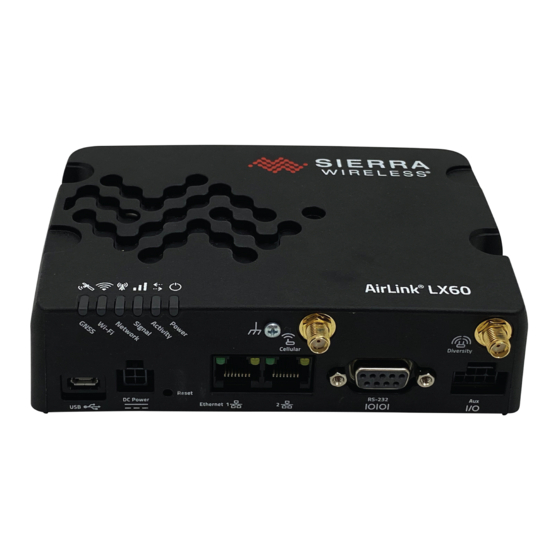
41.) Default Settings on page 35.) *Wi-Fi + GNSS model Side Panel Mini-SIM 2FF Card slot (See Insert the SIM Card on page 18) Figure 1-1: LX60 Connectors, LEDs and SIM Card Holder Rev. 2 June 2021 41111782... -
Page 9: Sample Power Consumption Scenarios
Introduction to the LX60 Sample Power Consumption Scenarios Table 1-1: Power Consumption Scenarios Scenario Radio Notes Cat-M Power Power Standby Mode — — 35 mW 35 mW (2.9 mA) (2.9 mA) Serial Idle Attached Serial enabled 800 mW 800 mW (66.6 mA) -
Page 10: Accessories
· Voltage input: 100–240 VAC · Current output: 1.5 A · Part number: 2000579 • I/O Auxiliary cable · Part number: 6001004 Warranty The LX60 comes with a 3-year warranty, and has an optional 2-year warranty extension. Rev. 2 June 2021 41111782... -
Page 11: Installation And Startup
2: Installation and Startup This chapter shows how to connect, install and start the Sierra Wireless LX60. It also describes the front panel LEDs, and I/O functionality. Note: Field wiring and connections in hazardous locations must be connected as per the wiring methods requirement for Class 2 circuits mentioned in the National Electric Code and the Canadian Electric Code. -
Page 12: Step 1-Insert The Sim Card
35 " Réinitialiser le LX60 aux paramètres d'usine par défaut " Note: Depending on where you are installing the LX60, you may want to mount the router before connecting the antenna, cables and power. Step 1—Insert the SIM Card If the SIM card has not already been installed, insert the SIM card into the router before connecting any external equipment or power to the router. -
Page 13: Step 2-Mount And Ground The Lx60 Chassis
There is adequate airflow • It is away from direct exposure to the elements, such as sun, rain, dust, etc. The LX60 has two mounting holes, as shown in Figure 2-2. Use appropriate mounting screws to secure it in place. -
Page 14: Step 3-Connect The Antennas
A ground wire is supplied with the unit. When using a different ground wire, to ensure a good grounding reference, connect one end of a short 18 AWG or larger gauge wire with a ring terminal connector to the ground terminal on the LX60 and connect the other end to your main grounding point. - Page 15 • Cellular antenna connector: Primary receive and transmit antenna connector • Cellular Diversity antenna connector: LTE MIMO and 3G Diversity The AirLink LX60 with Wi-Fi + GNSS also has: • One GNSS antenna connector • One reverse polarity SMA male connector for the Wi-Fi antenna.
-
Page 16: Recommended Antenna Separation
Note: In vehicle installations, separate antenna, data, and power cables from other wiring. Step 5—Connect the Power The AirLink LX60 comes with a 3 meter (10 ft.) DC power cable. You can also purchase an optional AC adapter. Electrical installations are potentially dangerous and should be performed by personnel Warning: thoroughly trained in safe electrical wiring procedures. -
Page 17: Cable Strain Relief
Sierra Wireless recommends using cable strain relief for installations in high-vibration environments. Place the cable strain relief within 200 mm (8 in.) of the LX60 to reduce the mass of cable supported by the power connector under vibration. Ideally, the strain relief mounting for the DC cable should be attached to the same object as the LX60, so both the router and cable vibrate together. -
Page 18: Power Connector On The Lx60
Software Configuration User Guide. Wiring Diagrams If you do not use the AC power adapter to power the LX60, you can wire the supplied DC cable to your power supply. You have various options for wiring power to the LX60, depending on your application. - Page 19 (unswitched) DC power source. • Pin 2 (Ground)—Use the black wire in the DC cable to connect Pin 2 to ground. See also Step 2—Mount and Ground the LX60 Chassis on page 13. • Pin 3 (On/Off control)—Connected to power...
-
Page 20: Vehicle Installation Considerations
2-8.) 7. Connect the white wire (On/Off control) on the DC power cable to the ignition signal from the vehicle. 8. Connect the DC power cable to the LX60. 9. Reconnect the vehicle’s battery: a. Connect the positive terminal first. - Page 21 • Pin 2 (Ground)—Use the black wire in the DC cable to connect Pin 2 to ground. See also Step 2—Mount and Ground the LX60 Chassis on page 13. • Pin 3 (On/Off) —Sierra Wireless recommends always using the On/Off wire (Pin 3) to turn the router off.
-
Page 22: Step 6 (Optional)-Connect The Vehicle Bus Cable
1.1 or later). AVTA is an AAF application that is used to send telemetry data to a 3rd party server. Note: An LX60 with Wi-Fi + GNSS running ALEOS 4.13.0 or later does not require a separate scanner for reporting of vehicle telemetry data (a Sierra Wireless AirLink Vehicle Telemetry kit, which includes an OBD-II scanner, is not required). -
Page 23: Step 7-I/O And Rs Configuration
Installation and Startup Step 7—I/O and RS Configuration The AirLink LX60 has five pins you can use for I/O and RS configuration: • Pin 4 on the power connector • Pins 2, 3, 6, and 7 on the auxiliary I/O connector ·... - Page 24 AirLink LX60 Series Hardware User Guide Table 2-3: I / O Pin-out Configuration Location Pin/Wire Digital Analog Digital Pull-up ACEmanager Color Configuration Auxiliary I/O 6/Yellow Digital 3 Connector /I/O Cable Analog 3 (SKU # 6001004) RS > Enable...
- Page 25 This may take approximately 30 seconds after the gateway is restarted or powered on. You can use the I/O pins in conjunction with events reporting to configure the LX60 to send a report when the state of the monitored router changes, for example when a switch is opened or closed.
- Page 26 AirLink LX60 Series Hardware User Guide You can connect any of these pins to a digital input to detect the state of a switch such as a vehicle ignition, or to monitor an external device such as a motion detector, a remote solar panel, or a remote camera.
- Page 27 Pins 2, 3, 6, and 7 on the auxiliary I/O connector. You can connect any of these pins to a dry contact switch. The dry contact switch is not available in Standby mode. LX60 Internal pull-up Pin 4 (power connector), or...
- Page 28 AirLink LX60 Series Hardware User Guide LX60 Internal pull-up Pin 4 (power connector), or resistor Pin 6 or 7 (I/O connector) Off (default)* Protection Circuitry Output Off (default)* * Configurable on the ACEmanager I/O tab Solar panel or battery Figure 2-14: Analog Input...
- Page 29 Installation and Startup Low Side Current Sink Output Low side current sink output, for example to drive a relay, is only available using Pin 4 on the power connector. LX60 Internal pull-up resistor Protection External solenoid/relay circuit Circuitry = 500 mA (Typ)*...
-
Page 30: Step 8-Check The Router Operation
0.5 V Step 8—Check the Router Operation 1. When power is supplied to the AirLink LX60 router, it powers up automatically, as indicated by the flashing LEDs. If it does not turn on, ensure that the: · Power connector is plugged in and supplying voltage greater than 9 VDC. -
Page 31: Led Behavior
ALEOS Software Configuration Guide (Serial chapter). Flashing Amber Traffic is being transmitted or received over both the WAN interface and the serial port. This behavior only appears if the LX60 is configured to display it. Refer to the ALEOS Software Configuration Guide (Serial chapter). Signal Solid Green Good signal (equivalent to 3–5 bars) -
Page 32: Ethernet Leds
Recovery mode a. May result from ALMS not reporting the R2C eSIM activation state (the LX60, the eSIM, and ALMS have not synchronized after device registration or a device reset), or status reports from ALMS have been disabled. Network or server issues may also result in an unknown activation state. -
Page 33: Step 9-Configure The Software
Installation and Startup Step 9—Configure the Software You can configure the ALEOS software on the LX60 using: • ACEmanager (browser-based application) • AirLink Management Service (cloud-based application) • AirLink Mobility Manager (unified software platform deployed in the enterprise data center) •... -
Page 34: Reboot The Lx60
AirLink LX60 Series Hardware User Guide • Location monitoring, including world map views • Complete ALEOS reporting and configuration, including historical views of ALEOS information • Configure individual routers or use templates to perform batch configurations of your AirLink routers •... -
Page 35: Reset The Lx60 To Factory Default Settings
ID, network password, custom APNs, low voltage standby are preserved by default. However, you can configure the LX60 Reset Mode to reset all values, including the user password. For more details, refer to the ALEOS Software Configuration User Guide (Admin chapter). - Page 36 AirLink LX60 Series Hardware User Guide To exit Recovery mode, if it has been inadvertently entered, do one of the following: • Press the reset button on the router to reboot it. • Click the Reboot button on the Recovery screen.
-
Page 37: Specifications
3: Specifications This chapter describes the LX60 Series router specifications. Certification and Interoperability Note: All certifications listed below are pending. Some are in progress; others are planned. Emissions / Immunity • Industry Canada • Safety CB Scheme • UL 60950 •... -
Page 38: Network Technology
47. Reliability MTBF calculations are performed per Telcordia “Reliability Prediction Procedure for Electronic Equipment” document number SR-332, Method I, Issue 3. The MTBF for the LX60 (Ground Fixed, 25°C) is 327,289 hours (37.36 years). Rev. 2 June 2021 41111782... -
Page 39: Environmental Testing
Specifications Environmental Testing Ingress protection rating is IP20. Test Method Category Description MIL-STD-810G, Vibration Frequency range: 5 Hz–500 Hz Test method 514.6 Spectrum level: 2.24G on all axes for 8 hours/axis Operating mode: powered on MIL-STD-810G, Mechanical Shock Half-sine 40G, 15–23 ms, Test method 516.6, (+/-X, +/-Y, +/-Z directions, 10 times per axis) Procedure 1... -
Page 40: Host Interfaces
Ethernet port, allowing access to the Internet and the LX60’s internal web server. This is the default setting. Virtual Serial Port: The LX60 behaves as if it was connected to a • standard serial port. The primary use of this interface is for the AT command line interface of ALEOS and for diagnostic access to the radio module. - Page 41 Specifications Serial Port 9-pin RS232 serial port connects directly to most computers or other • devices with a standard serial straight-through cable Note: If you have a DCE device, you need to use a null modem (cross-over) cable. Used for connecting serial devices and configuration •...
-
Page 42: Sim Card Interface
Non-inverting RS485_B Inverting SIM Card Interface • The LX60 has one 6-pin SIM socket for a mini-SIM (2FF) SIM card, operated at 1.8 V/ 3.3 V. • This interface is compliant with the applicable 3GPP standards for USIM. Mechanical Specifications... -
Page 43: Operating Voltage
Specifications Operating Voltage By default, the router is configured to enter Standby mode at 9 V. If you want to operate the router at less than 9 volts, power it on using at least 9 V, launch ACEmanager, go to Services >... -
Page 44: Gnss Technology
AirLink LX60 Series Hardware User Guide GNSS Technology Satellite channels Maximum 48 tracking channels and 2 fast acquisition channels Constellations • Galileo • GLONASS • BeiDou • QZSS • Protocol NMEA 0183 V3.0 Acquisition time (Time Hot start: 1 second •... -
Page 45: Wi-Fi Performance
Specifications Wi-Fi Performance Technology Frequency MIMO 20 MHz 40 MHz 80 MHz 802.11n 2.4 GHz 1 × 1 72 Mbps 5 GHz 1 × 1 100 Mbps 150 Mbps 802.11ac 5 GHz 1 × 1 87 Mbps 200 Mbps 433 Mbps a. -
Page 46: Wi-Fi Antenna Gain
Wi-Fi Antenna Gain The AirLink LX60 is compliant with the RF exposure requirements at 20 cm separation distance specified in EN 62311:2008 and 1999/519/EC for mobile exposure conditions, provided the maximum antenna gain does not exceed the limits given in the table below. -
Page 47: Radio Frequency Bands
Table 3-7, Table 3-8, Table 3-9, Table 3-10, and Table 3-11 is provisional. Table 3-6: LX60 Radio Module WP7601 North America and EMEA Radio Technology Band Frequencies Verizon Wireless Band 4 Tx: 1710–1755 MHz Rx: 2110–2155 MHz Band 13 Tx: 777–787 MHz... - Page 48 AirLink LX60 Series Hardware User Guide Table 3-8: LX60 Radio Module WP7607 EMEA Radio Band Frequencies Technology Generic Band 1 Tx: 1920–1980 MHz Rx: 2110– 2170 MHz Band 3 Tx: 1710–1785 MHz Rx: 1805–1880 MHz Band 7 Tx: 2500–2570 MHz...
- Page 49 Specifications Table 3-9: LX60 Radio Module WP7610 North America Radio Band Frequencies Technology Generic Band 2 Tx: 1850–1910 MHz Rx: 1930– 1990 MHz Band 4 Tx: 1710–1755 MHz Rx: 2110–2155 MHz Band 5 Tx: 824–849 MHz Rx: 869–894 MHz ...
- Page 50 AirLink LX60 Series Hardware User Guide Table 3-10: LX60 Radio Module WP7609 Australia and New Zealand Radio Band Frequencies Technology Generic Band 1 Tx: 1920–1980 MHz Rx: 2110– 2170 MHz Band 3 Tx: 1710–1785 MHz Rx: 1805–1880 MHz ...
- Page 51 Specifications Table 3-11: LX60 Radio Module WP7702 Worldwide Radio Module Firmware Band Frequencies Technology Generic Band 8 Tx: 880–915 MHz Rx: 925–960 MHz Band 12 Tx: 699–716 MHz Rx: 729 –746 MHz Band 13 Tx: 777–787 MHz Rx: 746 –756 MHz...
-
Page 52: Radio Module Conducted Transmit Power
AirLink LX60 Series Hardware User Guide Radio Module Conducted Transmit Power The following tables provide radio module conducted transmit power specifications. The radio module type is printed on the label on the bottom of the router and is available in ACEmanager (Status >... - Page 53 Specifications Table 3-15: Radio Module WP7609 Conducted Transmit Power Band Conducted Tx Notes Power (dBm) Bands 1, 3, 5, 7, 8, 28 +23±1 Connectorized (Class 3) WCDMA Bands 1, 5, 8 +23±1 Connectorized (Class 3) Table 3-16: Radio Module WP7610 Conducted Transmit Power Band Conducted Tx Notes...
-
Page 54: Gnss Bands Supported
AirLink LX60 Series Hardware User Guide GNSS Bands supported Table 3-18: GNSS Bands Supported Band Frequency 1575.42 MHz GLONASS 1597.52–1605.92 MHz Galileo 1575.42 MHz BeiDou 1561.098 MHz Rev. 2 June 2021 41111782... -
Page 55: Mechanical Specifications
Specifications Mechanical Specifications Front view 5.75 in. 1.5 in. Weight: 270 g (9.5 oz.) Top view 5.18 in. 1.6 in. 3.92 in. 5.75 in. Figure 3-3: LX60 Mechanical Specifications Rev. 2 June 2021 41111782... -
Page 56: Regulatory Information
Regulatory Information Important Information for North American Users Note: This equipment has been tested and found to comply with the limits for a Class B digital device, pursuant to part 15 of the FCC Rules. These limits are designed to provide reasonable protection against harmful interference in a residential installation. -
Page 57: Rf Exposure
RF radiation, the maximum antenna gain must not exceed the specifications listed below for the device used. Maximum Antenna Gain The antenna gain must not exceed the limits and configurations shown in the following tables: Table 4-1: LX60 WP7601 Maximum Antenna Gain Device Frequency Band FCC ID/IC Number N7NWP76A 2417C-WP76A... - Page 58 AirLink LX60 Series Hardware User Guide Table 4-3: WP7607/7609 Maximum Antenna Gain FCC ID/IC Number N7NWP76C 2417C-WP76C Device Frequency Band Maximum Antenna Gain (dBi) AirLink LX60 Must not exceed antenna gains due to RF exposure and ERP/EIRP limits, as listed in the module’s FCC grant.
- Page 59 Regulatory Information WEEE Notice If you purchased your AirLink LX60 in Europe, please return it to your dealer or supplier at the end of its life. WEEE products may be recognized by their wheeled bin label on the product label.
-
Page 60: Accessories
A: Accessories DC Power Cable (Black Connector) Table A-1: DC Power Cable DC Power Cable Part Number 2000522 Product Release 2016 Components: 1 UL2464 20 AWG × 4 core cable 4 Molex female crimp terminals /AWG 20-24, 250V, 5 A max, phosphor bronze ... -
Page 61: Ac Power Adapter (Black Connector)
Accessories AC Power Adapter (Black Connector) Table A-2: AC Power Adapter AC Power Adapter Part Number 2000579 Product Release 2016 AC Power Adapter Input Table A-3: Input Specifications Minimum Typical Maximum Input Input Voltage 90 VAC 100–240 VAC 264 VAC Input Frequency 47 Hz 50/60 Hz... -
Page 62: Ac Power Adapter Environmental Specifications
AirLink LX60 Series Hardware User Guide AC Power Adapter Environmental Specifications Table A-5: AC Power Adapter Environmental Specifications Operating Operating Temperature 0°C ~ 40°C (operates normally) Relative Humidity 10% ~ 90% Altitude Sea level to 2,000 meters Vibration 1.0 mm, 10–55 Hz, 15 minutes per cycle for each axis (X, Y, Z) -
Page 63: Ac Power Adapter Hazardous Substances
Accessories AC Power Adapter Hazardous Substances • EU Directive 2011/65/EU “RoHS” • EU Directive 2012/19/EU “WEEE” • REACH AC Power Adapter Energy Efficiency The AC adapter complies with International Efficiency Levels, as shown in Table A-7. Table A-7: AC Adapter Energy Efficiency Supplied Input No-load Power Average Active... -
Page 64: I/O Connector Cable
AirLink LX60 Series Hardware User Guide I/O Connector Cable Table A-8: I/O Connector Cable I/O Connector Cable Part Number 6001004 Product Release 2016 Components: 1 UL2464 5 core × 20 AWG cable 5 Molex female crimp terminals /AWG 20-24, 300VAC, 3A rating, phosphor bronze ... -
Page 65: Index
Index AC power adapter, specifications, 61 I / O Configuration, 23 Accessories, 10 I/O auxiliary connector, 23 ACEmanager, 33 pins, 23 AirLink Management Service, 33 Input ALEOS software, 33 Analog, 27 AMM, 34 Dry contact switch, 27 Analog input, 27 Ignition switch, 25 Antenna... - Page 66 AirLink LX60 Series Hardware User Guide Reset to factory default settings, 35 exposure, 57 specifications, 15 Screw Torque, 42 Serial connector pin-out, 41, 42 Serial port, 41 Software, configure, 33 Specifications, 37 Environmental, 37 GNSS, 44 Regulatory, 62 RF, 15...
Need help?
Do you have a question about the LX60 and is the answer not in the manual?
Questions and answers