Table of Contents
Advertisement
Quick Links
Single-phase Thyristor Unit
THV-1
Instruction Manual
Thank you for purchasing this RKC product. In order to
achieve maximum performance and ensure proper operation
of your new instrument, carefully read all the instructions in
this manual. Please place this manual in a convenient
location for easy reference.
SYMBOLS
: This mark indicates precautions that must be
WARNING
taken if there is danger of electric shock, fire,
etc., which could result in loss of life or injury.
: This mark indicates that if these precautions
CAUTION
and operating procedures are not taken,
damage to the instrument may result.
!
: This mark indicates that all precautions should
be taken for safe usage.
: This mark indicates important information on
installation,
procedures.
: This mark indicates supplemental information
on
installation,
procedures.
: This
mark
information may be located.
!
An external protection device must be installed if
failure of this instrument could result in damage to
the instrument, equipment or injury to personnel.
All wiring must be completed before power is turned
on to prevent electric shock, fire or damage to
instrument and equipment.
This instrument must be used in accordance with the
specifications
to
prevent
instrument and equipment.
This instrument is not intended for use in locations
subject to flammable or explosive gases.
Do not touch high-voltage connections such as
power supply terminals, etc. to avoid electric shock.
RKC is not responsible if this instrument is repaired,
modified
or
disassembled
factory-approved personnel. Malfunction can occur
and warranty is void under these conditions.
This product is manufactured on the assumption that it is
mounted
within
a
control
connections such as power supply terminals must be
enclosed in the control panel to avoid electric shock by
operating personnel.
All Rights Reserved, Copyright 2002, RKC INSTRUMENT INC.
IMR01M01-E5
handling
and
operating
handling
and
operating
indicates
where
additional
WARNING
fire
or
damage
by
other
CAUTION
panel.
All
high-voltage
All precautions described in this manual should be taken to
avoid damage to the instrument or equipment.
All wiring must be in accordance with local codes and
regulations.
Always use this product at the rated power supply voltage,
load current and power frequency.
All wiring must be completed before power is turned on to
prevent electric shock, instrument failure, or incorrect
action.
To prevent instrument damage or failure, protect the power
line and the input/output lines with a protection device such
as fuse, etc.
If this product is used for phase control, higher harmonic
noise may be generated. Therefore in this case, take such
measures as installing an isolation transformer and
separating the power line from the high-voltage line for
load drive.
Prevent metal fragments or lead wire scraps from falling
inside instrument case to avoid electric shock, fire or
malfunction.
Tighten each terminal screw to the specified torque found
in the manual to avoid electric shock, fire or malfunction.
For proper operation of this instrument, provide adequate
ventilation for heat dispensation.
Do not connect wires to unused terminals as this will
interfere with proper operation of the instrument.
Turn off the power supply before cleaning the instrument.
Do not use a volatile solvent such as paint thinner to clean
the instrument. Deformation or discoloration will occur. Use
a soft, dry cloth to remove stains from the instrument.
To avoid damage to instrument display, do not rub with an
abrasive material or push front panel with a hard object.
This manual assumes that the reader has a fundamental
knowledge of the principles of electricity, process control,
computer technology and communications.
The figures, diagrams and numeric values used in this
manual are only for purpose of illustration.
RKC is not responsible for any damage or injury that is
caused as a result of using this instrument, instrument
failure or indirect damage.
Periodic maintenance is required for safe and proper
operation of this instrument. Some components have a
limited service life, or characteristics that change over time.
Every effort has been made to ensure accuracy of all
information contained herein. RKC makes no warranty
expressed or implied, with respect to the accuracy of the
to
information. The information in this manual is subject to
change without prior notice.
No portion of this document may be reprinted, modified,
copied,
transmitted, digitized,
retrieved through any mechanical, electronic, optical or
other means without prior written approval from RKC.
than
1. CHECKING THE PRODUCT .................................2
2. CONFIRMATION OF THE MODEL CODE ...............2
3. PARTS DESCRIPTION .......................................3
4. MOUNTING ......................................................3
5. WIRING ............................................................6
6. SETTING .........................................................9
7. FUNCTIONS ...................................................14
8. ERROR OR ALARM DISPLAYS ...........................21
9. SPECIFICATIONS .............................................22
10. ACCESSORIES (OPTION) .................................23
®
NOTICE
stored, processed or
CONTENTS
Advertisement
Table of Contents

Related Manuals for RKC INSTRUMENT THV-1


Summary of Contents for RKC INSTRUMENT THV-1
-
Page 1: Table Of Contents
9. SPECIFICATIONS ………………………………………22 enclosed in the control panel to avoid electric shock by operating personnel. 10. ACCESSORIES (OPTION) ……………………………23 All Rights Reserved, Copyright 2002, RKC INSTRUMENT INC. RKC INSTRUMENT INC. ®... -
Page 2: Checking The Product
1. CHECKING THE PRODUCT When unpacking your new instrument, please confirm that the following items are included. If any item is missing, damaged, or if your manual is incomplete, please contact RKC sales office or the agent. • THV-1: 1 unit Accessories (option) •... -
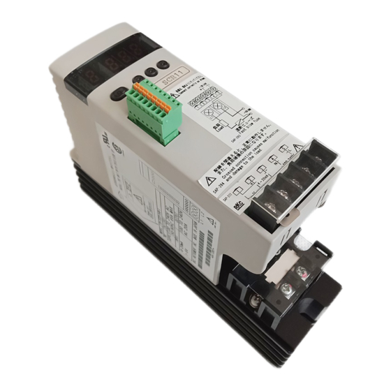
Page 3: Parts Description
3. PARTS DESCRIPTION The 20 A and 30 A types are used in the following figures for explanation, but the same explanations also apply to 45 A, 60 A, 80 A and 100 A types. Mounting positions (upper) Name Description (1) Display Display the input signal values (1) Display... - Page 4 4.2 Dimensions 20 A and 30 A types Unit: mm Mounting dimensions Dimensions 133.5 2-M5 Dimensions when the connector plug (optional) connected. When connecting the connector plug, install the thyristor by taking enough space for its wiring into account. Minimum space when mounted closely side by side. Some space for heat radiation is required in the vertical direction between the lower and upper ends of the instruments.
- Page 5 80 A and 100 A types Unit: mm Dimensions Mounting dimensions 158.5 104 ± 0.2 4-M5 Dimensions when the connector plug (optional) is connected. When connecting the connector plug, install the thyristor by taking enough space for its wiring into account. Minimum space when mounted closely side by side.
-
Page 6: Wiring
(4 kgf⋅cm) (16 kgf⋅cm) (38 kgf⋅cm) (90 kgf⋅cm) Wiring diagram of main circuit Power supply THV-1 100 to 240 V AC (50/60 Hz) Input and Always conduct wiring so that the power supply phase of the main circuit (L1) - Page 7 4 to 20 mA DC Voltage pulse input 0/12 V DC − − THV-1 input impedance THV-1 input impedance: 100 Ω 1 to 5 V DC, 0/12 V DC: 30 kΩ 0 to 10 V DC: 68 kΩ THV-1 THV-1...
- Page 8 For contact input, short connector For ON/OFF control, short connector pin No.2 with connector pin No.2 with connector pin No.5. pin No.5. Low limit setter High limit setter Controller Controller THV-1 connector ON/OFF signal ON/OFF signal THV-1 connector +5 V output Short Short...
-
Page 9: Setting
6. SETTING This chapter describes the display menus on the LED display. 6.1 Display Flowchart for Monitor and Setting Parameters The instrument has two monitor/setting modes. • Parameter group 1 includes parameters for both monitoring and setting such as Input Signal Monitor 1, Phase Angle Monitor, Phase/Zero-cross control selection, and others. - Page 10 6.2 Display Sequence 6.2.1 Selecting parameter group After power-on to the instrument, the display automatically goes to Input Signal Monitor 1 in Parameter Group 1. To go to Parameter Group 2 display, press and hold the Parameter Key for 2 seconds. Parameter group 1 Parameter group 2 Press the parameter...
- Page 11 Continued from the previous page. Parameter group 1 Name Parameter Setting range Factory Details Reference symbol page value Soft-start time 0.0 to 99.9 seconds Set the soft-start time. P. 14 Soft-down time 0.0 to 99.9 seconds Set the soft-down time. P.
- Page 12 Continued from the previous page. Parameter group 1 Name Parameter Setting range Factory Details Reference symbol page value 0 to 100 % Heater break Set the heater break alarm 1 set P. 17 alarm 1 set value 0: Heater break alarm 1 value.
- Page 13 Continued from the previous page. Parameter group 1 Name Parameter Setting range Factory Details Reference symbol page value 0: ON at alarm output Alarm output state Select whether open-collector selection 1: OFF at alarm output output is turned on or off when the heater break alarm is output.
-
Page 14: Functions
1: Internal manual mode Internal manual set value Input signal from controller closed ↔ Auto mode (Manual mode) THV-1 2: Internal manual mode Internal manual set value (fixed) Select manual mode type Example: Select manual mode with internal manual set value. - Page 15 Internal gradient External gradient scale The following two types of gradient setting are available. set value 1.00 • Internal gradient setting set by the THV-1 front keys • External gradient setting set by the external gradient setter 0.80 (external potentiometer) 0.60 0.40...
- Page 16 7.7 Output Mode for Phase Control When phase control is selected for a linearity (R: Resistance) load, one of the following four output types can be selected. The factory set value is proportional square voltage (electric power) to input. (The output mode setting is invalid when the control method is zero-cross control.) Proportional phase angle to input Proportional voltage to input Proportional square voltage...
- Page 17 7.8 Automatic Power Frequency Detection and Power Frequency Monitoring Function Automatic power frequency detection The instrument automatically detects a power supply frequency (50 Hz or 60 Hz) when the power is turned on. Detection range: 50 Hz = 45.0 to 54.9 Hz 60 Hz = 55.0 to 64.9 Hz Power frequency monitoring function This function monitors the power supply frequency and when it goes out of the detection range, the error message display...
- Page 18 Example of uses When each parameter is set to the following conditions • Maximum load current set value: 20 A • Heater break alarm 1 set value: 20 % • Number of alarm delay times: • Heater break alarm 2 set value*: 15 % * When the set value of heater break alarm 2 is used as a heater deterioration alarm Heater break alarm 1 set value = (Maximum load current set value) ×...
- Page 19 Setting Type 2 uses only the set value of heater break alarm 1. Set the alarm under the following conditions. • Heater break alarm 1 set value: Set the heater break alarm 1 set value to approximately 10 % of the maximum load current value.
- Page 20 Continued from the previous page. Control output Current transformer 20 A For the preset number of input value consecutive sampling cycles 18.5 A Heater break alarm 2 set value 16.5 A 16.5 A 16.5 A 16.5 A 16.5 A 17 A (heater deterioration) Heater break alarm 1 set value 16 A (heater break) Capture...
-
Page 21: Error Or Alarm Displays
8. ERROR OR ALARM DISPLAYS When the error or alarm occurs, the display changes to the error display. When two or more errors occur simultaneously, the error code numbers are totaled and displayed as one number. When any of the errors show below occurs, other displays will not be displayed. -
Page 22: Specifications
0 to 100 % (Set by the setter Internal gradient set value: 0 to 100 % (0.00 to 1.00) (Set by the THV-1 front keys) Output limiter (high) set value: 0.0 to 99.9 % (Set by the THV-1 front keys) Output limiter (low) set value: 0.0 to 99.9 %... -
Page 23: Accessories (Option)
10. ACCESSORIES (OPTION) Setter (Potentiometer, Knob and Scale plate) Unit: mm 40 50 60 M9 × 0.75 Set the potentiometer full counterclockwise and combine with a scale plate. φ16.1 When setting the knob on the scale plate, 13.5 10 10 φ2.8 align the arrow on the knob with 0 on the Knob... -
Page 24: Rkc Instrument Inc
The first edition: JUN. 2002 [IMQ00] The fifth edition: JUL. 2003 [IMQ00] HEADQUARTERS: 16-6, KUGAHARA 5-CHOME, OHTA-KU TOKYO 146-8515 JAPAN PHONE: 03-3751-9799 (+81 3 3751 9799) E-mail: info@rkcinst.co.jp RKC INSTRUMENT INC. ® FAX: 03-3751-8585 (+81 3 3751 8585) IMR01M01-E5 JUL. 2003...
Need help?
Do you have a question about the THV-1 and is the answer not in the manual?
Questions and answers