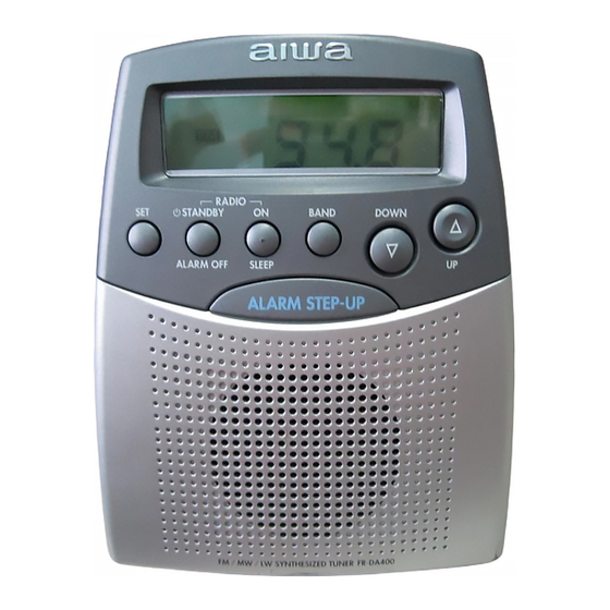
Aiwa FR-DA400 Service Manual
Hide thumbs
Also See for FR-DA400:
- Operating instructions manual (25 pages) ,
- Service manual (19 pages)
Table of Contents

Summary of Contents for Aiwa FR-DA400
- Page 1 All manuals and user guides at all-guides.com FR-DA400 EZ(S) SERVICE MANUAL RADIO RECEIVER This Service Manual is the "Revision Publishing" and replaces "Simple Manual" (S/M Code No. 09-008-348-9T2). S/M Code No. 09-008-348-9R2...
-
Page 2: Specifications
All manuals and user guides at all-guides.com SPECIFICATIONS • Design and specifications are subject to change without notice ACCESSORIES/PACKAGE LIST REF. NO PART NO. KANRI DESCRIPTION 1 8A-RU5-905-010 IB,EZ(EGF)C 1 8A-RU5-907-010 IB,EZ(PHNCZ)C 1 8A-RU5-906-010 IB,EZ(SID)C... -
Page 3: Electrical Main Parts List
All manuals and user guides at all-guides.com ELECTRICAL MAIN PARTS LIST REF. NO PART NO. KANRI DESCRIPTION REF. NO PART NO. KANRI DESCRIPTION C517 87-018-131-010 CAP,1000P C518 87-018-131-010 CAP,1000P 8A-RUA-605-010 IC,CXA1619BS C521 87-A11-144-080 CAP,TC U 0.1-50 K B S7-172-340-1A0 IC,LC72343G-9961 C523 87-018-131-010 CAP,1000P... -
Page 4: Chip Resistor Part Code
All manuals and user guides at all-guides.com • Regarding connectors, they are not stocked as they are not the initial order items. The connectors are available after they are supplied from connector manufacturers upon the order is received. CHIP RESISTOR PART CODE Chip Resistor Part Coding Figure Resistor Code... - Page 5 All manuals and user guides at all-guides.com BLOCK DIAGRAM-1 (MAIN) BLOCK DIAGRAM-2 (CPU)
- Page 6 All manuals and user guides at all-guides.com WIRING-1 (CONNECTION DIAGRAM) WIRING-2 (MAIN) TF401 MAIN C.B (PARTS SIDE) ACP401 6F22 R502 NOTE...
- Page 7 All manuals and user guides at all-guides.com SCHEMATIC DIAGRAM-1 (MAIN) T403 L403 L404 MAIN C.B LW FREQ. RANGE ADJ. FM TRACKING ADJ. FM FREQ. RANGE ADJ. C524 VOLUME SVC251 0.001 L402,TC402 LW TRACKING ADJ. L401,TC401 MW TRACKING ADJ. T401 SVC342 MW FREQ.
- Page 8 All manuals and user guides at all-guides.com WIRING-3 (LCD) WIRING-4 (KEY) KEY C.B (CONDUCTOR SIDE)
- Page 9 All manuals and user guides at all-guides.com SCHEMATIC DIAGRAM-2 (LCD/KEY) LCD C.B 220/6.3 LC72343 KEY C.B 47/6.3 NM : No Mount...
-
Page 10: Electrical Adjustment
All manuals and user guides at all-guides.com ELECTRICAL ADJUSTMENT VOLTAGE CHART... - Page 11 All manuals and user guides at all-guides.com...
-
Page 12: Transistor Illustration
All manuals and user guides at all-guides.com IC BLOCK DIAGRAM IC, CXA1619BS TRANSISTOR ILLUSTRATION E C B E C B E C B 2SC1740 DTA114YS 2SC1923 2SK880 2SC1815 2SC2001 PE8050 PE8550 2SD1468 2SA1015 D G S DTC114YK DTC114ES 2SC4116 2SC2458 2SK118... - Page 13 All manuals and user guides at all-guides.com IC DESCRIPTION IC, LC72343G Pin No. Pin Name Description XOUT Connections for a 75kHz crystal oscillator element. TEST2 IC test pins. These pins must be tied to ground. Special-purpose key return signal input port. Special-purpose key source signal output port.
- Page 14 All manuals and user guides at all-guides.com Pin No. Pin Name Description ________ System reset input. HCTR Universal counter dedicated input port. — Power supply pin. FMIN FM VCO (local oscillator) input. AMIN AM VCO (local oscillator) input. — Ground pin. The main charge pump output.
-
Page 15: Equipment Connection Diagrams
All manuals and user guides at all-guides.com EQUIPMENT CONNECTION DIAGRAMS LCD DISPLAY... -
Page 16: Mechanical Exploded View
All manuals and user guides at all-guides.com MECHANICAL EXPLODED VIEW 1/1 PLATE, SILICON PLATE A PC 62-46-0.5 P.W.B SH, LCD FELT, LCD P.W.B BAR-ANT P.W.B... -
Page 17: Mechanical Parts List
All manuals and user guides at all-guides.com MECHANICAL PARTS LIST 1/1 REF. NO PART NO. KANRI DESCRIPTION REF. NO PART NO. KANRI DESCRIPTION 1 8A-RU5-003-010 PANEL,FRONT EZ S 16 8A-RU3-201-010 HLDR,DIS 2 8A-RU3-013-010 WINDOW,LCD 17 8A-RU3-208-010 HLDR,BAR-ANT 3 8A-RU5-001-010 CABI,FRONT EZ S 18 8A-RU3-209-010 FOOT,RUBBER 4 8A-RU3-008-010... - Page 18 All manuals and user guides at all-guides.com 2–11, IKENOHATA 1–CHOME, TAITO-KU, TOKYO 110-8710, JAPAN TEL:03 (3827) 3111 H251701 Printed in Singapore...


Need help?
Do you have a question about the FR-DA400 and is the answer not in the manual?
Questions and answers