
Subscribe to Our Youtube Channel
Related Manuals for Kamstrup MAXICAL III


Summary of Contents for Kamstrup MAXICAL III
- Page 1 5511-229 GB/98.06/Rev. B1 ® MAXICAL I I I ® MAXICAL User’s Manual 5511-229/Rev. B1 ENGLISH...
- Page 2 ® MAXICAL 5511-229 GB/98.06/Rev. B1...
-
Page 3: Table Of Contents
5511-229 GB/98.06/Rev. B1 ® MAXICAL I I I 1. Table of Contents Table of Contents Design and Areas of Application 2.1. Display 2.2. Calculation 2.3. Logging Peak Values 2.4. Measuring Temperature 2.5. Permanent Memory 2.6. Information Codes 2.7. Optical data acquisition 2.8. - Page 4 ® MAXICAL 5511-229 GB/98.06/Rev. B1 Tariff Functions Programming Tariff and Alarm Limits Data Setup 10. Data Communication 10.1 Data Strings and Functions 10.2 Data Strings 10.3 Data Acquisition via Connection Terminals 11. Programming (Windows) software 66-99-210 11.1 Computer and Printer Requirements 11.2 Installing the Software ®...
-
Page 5: Design And Areas Of Application
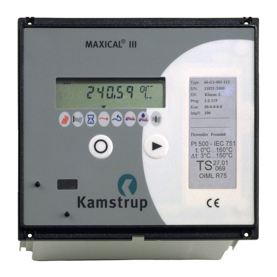
5511-229 GB/98.06/Rev. B1 ® MAXICAL I I I 2. Design and Areas of Application ® MAXICAL III is designed for measuring, calculating and registering energy consumption in large heat installations with water as the heat transferring agent. Typical applications include main heat metering at CHP (cogeneration heat and power) suppliers, heat metering through transmission nets or exchange stations. - Page 6 ® MAXICAL 5511-229 GB/98.06/Rev. B1 Press the right or left key, as appropriate, to move from one displayed value to another. Note that only values selected during configuration can be displayed [DD]. The peak value displayed is the highest average of 1...120 minutes actual values recorded over the last 24 hour period.
-
Page 7: Calculation
5511-229 GB/98.06/Rev. B1 ® MAXICAL I I I 2.2. Calculation ® In MAXICAL III, thermal energy is calculated after a given amount of water has been recorded. The typical integration interval is 10 litres with a Qn 1.5 m³/h flow meter and 1 m³, if a Qn 120 m³/h to Qn 1400 m³/h flow meter is connected. -
Page 8: Permanent Memory
® MAXICAL 5511-229 GB/98.06/Rev. B1 The differential temperature is accurately calculated throughout the whole measuring range - even with cooling down to 0.01°C. Accuracy is, however, slightly affected below Dt=3°C. If a negative differential temperature is registered, this will be per- ceived as 0.00°C. -
Page 9: Information Codes
5511-229 GB/98.06/Rev. B1 ® MAXICAL I I I 2.6. Information Codes During normal operation the information code will be 000. If one or more of the following faults occurs, the letter “E” will be shown in the current display, and the Infocode relay will be deenergized. The information codes, which will be added together if more than one is activated, can be displayed as required. -
Page 10: Voltage Supply And Back-Up
A read-out head, type 66-99-102, with a 9-pole D-sub plug is used for data acquistion and when configuring the meter from a compu- ter. Data acquisition is also possible with Kamstrup Energi’s hand- held terminal, MULTITERM III. Kamstrup Energi’s software ®... -
Page 11: Panel Installation
5511-229 GB/98.06/Rev. B1 ® MAXICAL I I I 3. Panel Installation 19" Rack version with front dimensions Q144 version for frontal fitting in control 142 x 128mm, or 28 TE & 3 HE, panel. Panel cut-out: 138 x 138 ± 0.5 mm. corresponding to 1/3 Rack. -
Page 12: General Installation Requirements
® MAXICAL 5511-229 GB/98.06/Rev. B1 4.1 General Installation Requirements ® MAXICAL III must not be installed in an area where the ambient temperature exceeds 0...+55°C. If the average ambient tempera- ture lies above +35°C, the internal lithium back-up cell should be replaced every two years. -
Page 13: Temperature Sensors
5511-229 GB/98.06/Rev. B1 ® MAXICAL I I I 4.3 Temperature sensors (1-8) ® MAXICAL III is supplied for use with either Pt100 or Pt500 temperature sensors, indicated on the front plate by either 66-F; Pt100 input or 66-G; Pt500 input. Screen connection Insulated screen Return pipe... -
Page 14: Average Measurement
® MAXICAL 5511-229 GB/98.06/Rev. B1 If the difference in length (Dl) between the two sensors is greater, a correspondingly bigger cable cross sectional area (Q) should be used, as indicated in the following diagram: Provided the difference in length between the flow and return sensor cables - as shown in the diagram are strictly observed, the error increment on the differential temperature will be less than 0.02 K. - Page 15 5511-229 GB/98.06/Rev. B1 ® MAXICAL I I I Example 1 4 sensor sets - with different sensor tube lengths - are installed in both the flow and return lpipes. The four sensors are connected both in series and parallel, so that the original sensor characteris- tics are maintained.
- Page 16 III. As with example 1, only paired sensors sets should be used. 4.4 Flow Meter Input (9-11) This flow meter input can be used by to mechanical meters with Reed-switch output, mechanical meters with electronic pick-ups or ® Kamstrup Energi’s ultrasonic meters: ULTRAFLOW...
- Page 17 5511-229 GB/98.06/Rev. B1 ® MAXICAL I I I ® The flow meter connected must use MAXICAL III’s pulse separation (CCC-table). Furthermore, the internal flow switch must be set to 9-11 (please refer to chapter 4.6). With reed switch With electronic pick-up With ULTRAFLOW ®...
-
Page 18: Flow Meter Input
® MAXICAL 5511-229 GB/98.06/Rev. B1 4.5 Flow Meter Input (75-76) This flow meter input is galvanically separated via an optocoupler and designed for electronic flow meters with active frequency output of max. 5 kHz or 10 kHz. The flow meter’s frequency output must have an amplitude of 12...30V. - Page 19 5511-229 GB/98.06/Rev. B1 ® MAXICAL I I I NOTE: In case of installation in noisy surroundings we recommend that screened cable is used as shown in the installation drawings.
-
Page 20: Flow Meters With Analogue Output
Using flow meters with analogue output (4 … 20 mA) an I/F Blue converter is needed to convert the measuring current to flow pulses. Kamstrup’s DIN rail module type 79-68-411 is suitable for this purpose. In this case flow meter 9-10-11 is to be used together with CCC codes 3xx. - Page 21 5511-229 GB/98.06/Rev. B1 ® MAXICAL I I I Selecting Flow Meter Input: Place the print switch as shown above, to change over between two flow meter inputs (refer to chapters 4.4 and 4.5). Selecting Pulse Duration ® When you take delivery of MAXICAL III, pulse outputs for energy and water (16-19) will be set at 0.1 sec.
-
Page 22: Pulse And Data Outputs
® MAXICAL 5511-229 GB/98.06/Rev. B1 4.7 Pulse and Data Outputs (16-19) (62-64) The pulse outputs for energy and water, on terminals 16-19, normally emit one pulse for each display count, e.g. 0.01 MWh and 0.1 m³ (please refer to the CCC tables in chapter 6). Furthermore a 10:1 divider can be programmed (see chapter 6.8) N.B: If an electromechanical meter is used a diode has to be connected in parallel above the coil. -
Page 23: Analogue Outputs
66-99-210. All outputs should - in consideration of EMC - be laid as a complete cable - or couples via isolation amplifiers (please refer to Kamstrup Proces’ data sheet P50 749 - Loop Isolator). -
Page 24: Relay Outputs
® MAXICAL 5511-229 GB/98.06/Rev. B1 4.9 Relay Outputs (88-93) Relay outputs on the combined analogue and relay module are used for monitoring both the process and the integrator. Infocode is connected between terminals 92 and 93 when the ® voltage supply is in order and MAXICAL III has registered no system error - corresponding to info = 000. -
Page 25: Compiling The Type Number
No analogue and relay module required Analogue & Relay module No Com. module required No sensors required Pt500 pocket sensor set w/1.5 m cable Pt100 pocket sensor set w/0.5 m cable Q144 Panel model 19” Rack model Delivery code (to be determined by Kamstrup A/S) -
Page 26: Prog. Config And Data Summary
® MAXICAL III’s many functions are determined during program- ming - which can be done either by Kamstrup A/S, your local distributor, the heat supplier or by a service engineer. Programming is divided into three groups: PROG, CONFIG and DATA. Legal measuring parameters PROG may only be changed when the program block is V=0. -
Page 27: Ccc-Table For Maxical ® Iii
5511-229 GB/98.06/Rev. B1 ® MAXICAL I I I ® 6.1 CCC-Table for MAXICAL No. of Decimals in the Display Pre- Flow- kWh MWh GJ m³ l/h m³/h kW MW l/Pulse Pulse/l Type counter factor 786420 1-3,5 1966050 1,5-6 786420 2,5-30 1966050 0,04 6-60... -
Page 28: Ccc-Table For Maxical
® MAXICAL 5511-229 GB/98.06/Rev. B1 ® 6.2 CCC-Table for MAXICAL No. of Decimals in the Display Pre- Flow- kWh MWh GJ m³ l/h m³/h kW MW l/Pulses Pulses/l Type counter factor 307195 0,03906 25,6 1,5/2,5 GWF 1280 614390 0,078125 12,8 1140 689842 0,087719... - Page 29 5511-229 GB/98.06/Rev. B1 ® MAXICAL I I I ® 6.3 CCC-Table for MAXICAL CCC-codes 300-303 are used for flow meters with active fre- quency output, programmed to 5 kHz @ Qmax. CCC Sep. Pre- Flow- No. of Decimals in the Display counter factor kWh MWh GJ...
-
Page 30: Dd< Configuration Of Display Values
® MAXICAL 5511-229 GB/98.06/Rev. B1 6.4 >DD< Configuration of Display Values Energy ***) Water Hour Counter FLOW RETURN Power Peak Power Flow Peak Flow All Info Info (-2) TA 2 ***) TL 2 TA 3 ***) TL 3 Alarm limits Customer ID No. -
Page 31: E< Configuring Multi-Tariff
5511-229 GB/98.06/Rev. B1 ® MAXICAL I I I 6.5 >E< Configuring Multi-Tariff Tarif Type Tariff Limits No active tariff Power controlled tariff TL2 < TL3 Flow controlled tariff TL2 < TL3 Cooling tariff TL3 < TL2 Return temperature tariff TL2 < TL3 Average temperature tariff Remote controlled tariff Clock controlled tariff... - Page 32 ® MAXICAL 5511-229 GB/98.06/Rev. B1 7. Tariff Functions ® MAXICAL III has two extra energy registers: TA2 and TA3, which can be used to accummulate energy, determined by the preprogrammed tariff parameters, parallel to the main register. The measuring unit for TA2 and TA3 is always the same as the main register, i.e.
- Page 33 5511-229 GB/98.06/Rev. B1 ® MAXICAL I I I Additionaly, the tariff provides the works with valuable statistical data, when calculating new plant activities. E=2) Flow-controlled tarif When the actual water flow (Q) - in l/h or m³/h - is larger than TL2, but smaller than TL3, thermal energy is counted in TA2, parallel to the main register.
- Page 34 ® MAXICAL 5511-229 GB/98.06/Rev. B1 The cooling tariff can be used as a basis for differential consumer billing. Minimal cooling (where the differ- ence between the flow and return temperatures is only small) is uneconomical for the heat supplier. E=5) Return temperature tariff When the actual return temperature (t ), in °C, is larger...
- Page 35 5511-229 GB/98.06/Rev. B1 ® MAXICAL I I I E=8) Remote-controlled tariff The above tariff types are all internal tariffs, managed ® by the integrator. MAXICAL III’s tariff registers; TA2 and TA3, can also be controlled remotely via data communication. Three different data commands (TAR0, TAR2 and TAR3) can be used to control the tariffs, e.g.
- Page 36 ® MAXICAL 5511-229 GB/98.06/Rev. B1 8. Programming Tariff and Alarm Limits All tariff limits, alarm limits and analogue outputs measuring ® values in MAXICAL III must be programmed as digits and decimals - but without the decimal point. Temperature limits (E=3 and E=5, H=3 and H=5 plus A3 and A4) must always be entered in °C with two decimals.
- Page 37 5511-229 GB/98.06/Rev. B1 ® MAXICAL I I I CCC No. E=1, H=1, A1 Programming E=2, H=2, A2 Programming Power (TL3 > TL2) Limits: Flow (TL3 > TL2) Limits: 0,001...1,000 MW 1...1000 0,01...5,00 m 1...500 0,001...1,000 MW 1...1000 0,01...9,00 m 1...900 0,01...9,00 MW 1...900 0,1...50,0 m...
- Page 38 ® MAXICAL 5511-229 GB/98.06/Rev. B1 CCCNo E=1, H=1, A1 Programming E=2, H=2, A2 Programming Power (TL3 > TL2) Limits: Flow (TL3 > TL2) Limits: 0,1...750,0 kW 1...7500 1...5000 l/h 1...5000 0,1...1500,0 kW 1...15000 1...10000 l/h 1...10000 0,1...1800,0 kW 1...18000 1...12000 l/h 1...12000 0,001...3,000 MW 1...3000...
- Page 39 Current Date YY.MM.DD The current date is programmed from the internal clock in the computer. 10th February, 1997 is written as 97.02.10. The data can also be changed via Kamstrup’s hand-held terminal, MULTITERM III. Current Time HH.MM.SS The current time is programmed from the internal clock in ®...
- Page 40 MAXICAL III can be accessed (V=0). Kamstrup’s read-out head, type no. 66-99-102, can be connected to a standard PC (IBM compatible) with Windows 3.1 - or a more recent version. Use Kamstrup’s programming software (66-99- 210) for programming - please read chapter 11 for further infor- mation on the programming software.
- Page 41 5511-229 GB/98.06/Rev. B1 ® MAXICAL I I I 10.1 Data Strings and Functions When the computer connected sends a recognisable request string, ® MAXICAL III responds by sending a data string 1-2 seconds after the request has been received. ® MAXICAL III’s data acquisition uses the following communication set-up:...
- Page 42 ® MAXICAL 5511-229 GB/98.06/Rev. B1 Normal data 2: -> / # 2 [300 BAUD] <- Customer No., TA2, TL2, TA3, TL3, Alarm Limit, 0, Prog. No., Config. No., Date — [1200 BAUD] Read-out data: -> / # 3 [300 BAUD] <- Customer No., Target Date, Energy, Water, TA2, TA3, AL, 0, 0...
- Page 43 5511-229 GB/98.06/Rev. B1 ® MAXICAL I I I 10.3 Data Acquisition via Connection Terminals Serial data communication - with the same function as the optical ® read out head - can be connected to the right of MAXICAL III, where all the connection terminals are placed. This means that both programming and data acquisition is possible via this data port.
- Page 44 ® MAXICAL 5511-229 GB/98.06/Rev. B1 The RS-232 adapter, shown above, is integrated in the data cable shown - type no. 66-99-106, making computer connection possi- ble. 11. Programming (Windows) software 66-99-210 ® MAXICAL III is 100% based on micro-processor technique, which means that all integration functions can be programmed.
- Page 45 LTP1. The printer must be suitable for Windows and for printing small labels. Kamstrup A/S recommend OKI 610ex, OKI 410ex or HP4 laser printer. ® The original labels for MAXICAL III can be ordered from Kamstrup A/S - product No.
- Page 46 ® MAXICAL 5511-229 GB/98.06/Rev. B1 11.4 Reading MAXICAL ® III’s Set-up Start the program by double-clicking with the left-hand button of ® the mouse on the MAXICAL III icon. Establish serial data communication, as described, and click on Read Meter. After a short wait the data transmitted will be displayed on the computer monitor.
- Page 47 5511-229 GB/98.06/Rev. B1 ® MAXICAL I I I 11.8 Screen Menu NOTE: ® If MAXICAL III is in operation during programming, the actual displays and analogue outputs for power and flow will show excessively high values for a few seconds. Analogue measured values may have a slightly lower value with Read meter than with Programming due to the integrator’s internal resolution, i.e.
- Page 48 ® MAXICAL III’s front panel has a void-label - placed by Kamstrup A/S - which prevents tampering. Temperature sensors with DIN-heads, shape B, can be sealed as shown below. The seal ensures that the top cannot be removed. If sensor pockets are used in addition to sensor tubes, these too must be sealed.
- Page 49 5511-229 GB/98.06/Rev. B1 ® MAXICAL I I I 13. Verification Quick-figure ® The Quick-figure is used when verifying MAXICAL III. The meter’s highest resolution is defined as the Quick-figure. The Quick-figure can be read in two ways: ® 1) In MAXICAL III’s display Select the next but last display - using the key on the left of ®...
- Page 50 ® MAXICAL 5511-229 GB/98.06/Rev. B1 x Dt x k [MJ] STUCK [GJ] 1000 [kWh] 3,6kk [MW] 3600 is the water quantity recorded (or simulated) during ® verification. E.g., if MAXICAL III has a Qn 1.5 m³/h flow meter and a CCC code of 119, the integrator will be pro- grammed to receive 100.0 volume pulses pr.
- Page 51 5511-229 GB/98.06/Rev. B1 ® MAXICAL I I I The k-factor stated in the table, is the basis for energy calculation in MJ, and must, therefore, be converted - using the formulae stated earlier, when the energy is required in other units. NB.: Precision resistors can be used for testing and verifying ®...
- Page 52 ® MAXICAL 5511-229 GB/98.06/Rev. B1 where Q and Q can be seen in the following Quick table: CCC-code (read chapter 6.1 - 6.3) Decimals with ] display 000, 001, 002, 108, 109, 110, 111, 112, 115, 116, 117, 118, 119, 121, 122, 123, 124, 125, 126, 132, 133, 134, 136, 139, 156, 164, 165, 165, 300, 310 2.388.900...
- Page 53 5511-229 GB/98.06/Rev. B1 ® MAXICAL I I I 13.3 Nominal quick-figure ® The nominal quick-figure for verification of MAXICAL III can be calculated using the formula stated on page 50, provided ideal conditions prevail. Nominal quick-figures can naturally only be used as a guideline or for testing functions - the quick-figure must be corrected for actual temperature deviations etc.
- Page 54 Send meter to repair Flow meter installed wrong way Re-install correctly ® Incorrect programming Reprogram MAXICAL III or send to Kamstrup for checking Check flow meter setting Incorrect temperature display Faulty temperature sensor Replace sensor pair Poor cable joints Check joints...
- Page 55 III is once again ready for operation. NB.: ® Remember to reset MAXICAL III’s internal clock subsequent to replacing the back-up cell. The clock can be set via the program- ming software, 66-99-210 or by means of Kamstrup’s hand-held terminal, MULTITERM III.
- Page 56 ® MAXICAL 5511-229 GB/98.06/Rev. B1 14.3 Inserting Analogue and Relay Module An analogue and relay module (66-x0) can easily be fitted into an ® existing MAXICAL III. The module has 4 active analogue outputs (4...20 mA) and two relay outputs for info code alarm and limit switches respectively.
- Page 57 I I I 15. Disposing of Energy Meters Kamstrup’s energy meters are designed for many years reliable operation. But all good things must come to an end - and a worn- out energy meter should be disposed of with as much considera- tion to the environment as possible.
- Page 58 ® MAXICAL 5511-229 GB/98.06/Rev. B1...
Need help?
Do you have a question about the MAXICAL III and is the answer not in the manual?
Questions and answers