Stahl 8549/1 Operating Instructions Manual
Load and motor switch, load-break switch
Hide thumbs
Also See for 8549/1:
- Operating instructions manual (49 pages) ,
- Operating instructions manual (60 pages)

Subscribe to Our Youtube Channel
Related Manuals for Stahl 8549/1


Summary of Contents for Stahl 8549/1
- Page 1 Betriebsanleitung/Operating Instructions Last- und Motorschalter, Lasttrennschalter Load and Motor Switch, Load-Break Switch > 8549/1...
- Page 3 Betriebsanleitung Last- und Motorschalter, Lasttrennschalter > 8549/1...
-
Page 4: Table Of Contents
Transport, Lagerung und Entsorgung ..............10 Montage ......................10 Installation ......................16 Inbetriebnahme ....................20 Wartung .......................20 Zubehör und Ersatzteile ..................21 EG-Konformitätserklärung ...................23 Allgemeine Angaben 2.1 Hersteller R. STAHL Schaltgeräte GmbH Am Bahnhof 30 74638 Waldenburg Germany Tel.: +49 7942 943-0 Fax: +49 7942 943-4333 Internet: www.stahl-ex.com... -
Page 5: Allgemeine Sicherheitshinweise
Warnhinweise sind in dieser Betriebsanleitung nach folgendem Schema gegliedert: WARNUNG Art und Quelle der Gefahr! Mögliche Folgen. Maßnahmen zur Vermeidung der Gefahr. Sie sind immer mit dem Signalwort „WARNUNG“ und teilweise mit einem gefahrenspezifischen Symbol gekennzeichnet. 168779 / 854960300010 Last- und Motorschalter, 2011-09-23·BA00·III·de·02 Lasttrennschalter 8549/1... -
Page 6: Vorgesehener Einsatzbereich
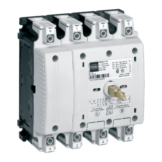
Anforderungen gemäß IEC/EN 60079-0 entspricht, eingebaut sein. Aufbau und Funktion Der Last- und Motorschalter Typ 8549/1 ist in den Varianten 8549/1-3. (3-polig) und 8549/1-4. (3-polig+N) erhältlich. Um einen 6-poligen Schalter zu erreichen, können zwei 3-polige Schalter über einen ... -
Page 7: Technische Daten
50 kA bei Schutz durch Sicherung I (IEC/EN 60947-3) Zuordnungsart 2 (gemäß IEC/EN 60947-4-1) Bemessungskurzzeit- 2,7 kA (IEC/EN 60947-3) stromfestigkeit Icw Max. Verlustleistung 10,8 W pro Pfad Lebensdauer Mechanisch Schaltspiele Elektrisch 20.000 Schaltspiele 168779 / 854960300010 Last- und Motorschalter, 2011-09-23·BA00·III·de·02 Lasttrennschalter 8549/1... - Page 8 (AWG 16 ... AWG 14), ein-, feindrähtig Material Schaltkammer Epoxidharz Obere Gehäuseteile Kontakte Silber-Zinnoxid Gewicht 3-polig: 4,5kg 3-polig + N: 5,9 kg Schutzart IP20 (IEC/EN 60529, fingersicher von oben) Schaltdrehmoment ca. 3,5 Nm Last- und Motorschalter, 168779 / 854960300010 Lasttrennschalter 8549/1 2011-09-23·BA00·III·de·02...
- Page 9 Technische Daten Umgebungstemperatur 8549/1-.1: - 30 ... + 80 °C 8549/1-.2: - 50 ... + 80 °C abhängig von Bemessungsbetriebsstrom, Leiterquerschnitt und Temperaturklasse: 8549/1-3., 3-polig: Temperaturklasse und Umgebungstemperatur Bemessungs- Leiterquerschnitt betriebsstrom ( 45 °C ( 60 °C ( 65 °C...
- Page 10 Technische Daten Maßzeichnungen (alle Maße in mm) - Änderungen vorbehalten 5,50 5,50 14237E00 14238E00 8549/1, 3-polig 8549/1, 3-polig + N Last- und Motorschalter, 168779 / 854960300010 Lasttrennschalter 8549/1 2011-09-23·BA00·III·de·02...
- Page 11 Maß „A“ Montagesatz Schalt- Einbau in Gehäuse welle 183,2 mm 8549A0307-2 82 mm 8146/...5 und 8125/...5 143,2 mm 8549A0307-1 42 mm 8146/...3 und 8125/...3 5,50 14239E00 8549/1, 3-polig + N + PE 168779 / 854960300010 Last- und Motorschalter, 2011-09-23·BA00·III·de·02 Lasttrennschalter 8549/1...
-
Page 12: Transport, Lagerung Und Entsorgung
Gehäuse der Zündschutzart „erhöhte Sicherheit“ einbauen. 7.1 Montagebohrungen anbringen Einzelschalter Die Montagebohrungen immer in Abhängigkeit vom Zentrum der Schaltwelle (Z) anbringen. Montagebohrungen 8548 (alt) Montagebohrungen 8549/1, 3-polig Montagebohrungen 8549/1, 3-polig+N oder 3-polig+PE-Klemme Montagebohrungen 8549/1, 3-polig+N+PE-Klemme oder 3-polig+N-Klemme+PE-Klemme 14235E00 Abb. - Page 13 Abb. 7-2: Bohrbild für zwei Schalter mit Parallelantrieb 6 Gewindebohrungen M5 in Montageplatte schneiden. 7.2 PE-Klemme und/oder N-Klemme montieren (optional) Beim Schalter 8549/1, 3-polig, können optional eine N-Klemme und/oder eine PE-Klemme montiert werden. Beim Schalter 8549/1, 3-polig+N, kann optional eine PE-Klemme montiert werden. 12434E00 Abb.
- Page 14 Abdeckung (1) des Einbauschachts (3) mit Schraubendreher oder Messer vorsichtig entfernen. Hilfskontakt (2) in Einbauschacht einsetzen und vorsichtig einrasten. Beigefügtes Schaltbild mit entsprechender Schaltfunktion auf Typschild des Schalters kleben. Last- und Motorschalter, 168779 / 854960300010 Lasttrennschalter 8549/1 2011-09-23·BA00·III·de·02...
- Page 15 Die Schaltwelle muss separat bestellt werden. Größe Länge für Gehäuse Xmin Xmax Bestellnummer 42 mm 8125/...3, 8146/...3 117,20 121,20 8549A0307-1 82 mm 8125/...5, 8146/...5 136,20 140,20 8549A0307-2 12437E00 Abb. 7-6: Schaltwellen 168779 / 854960300010 Last- und Motorschalter, 2011-09-23·BA00·III·de·02 Lasttrennschalter 8549/1...
- Page 16 Spannstift (2) vorsichtig mit einer Zange einpressen. Zwei Schalter mit Parallelantrieb Der Parallelantrieb muss separat bestellt werden. 12439E00 Abb. 7-8: Schaltwellen montieren Schaltwellen (1) in Schalter einsetzen. Spannstift (2) vorsichtig mit einer Zange einpressen. Last- und Motorschalter, 168779 / 854960300010 Lasttrennschalter 8549/1 2011-09-23·BA00·III·de·02...
- Page 17 Schalter setzen. Muttern M6 (3) mit 4,5 Nm anziehen. 7.7 Gehäusedeckel mit Betätigungsvorsatz montieren Gehäusedeckel mit montiertem Betätigungsvorsatz senkrecht auf Gehäuse/Welle setzen. Befestigungsschrauben des Gehäusedeckels anziehen. 168779 / 854960300010 Last- und Motorschalter, 2011-09-23·BA00·III·de·02 Lasttrennschalter 8549/1...
-
Page 18: Installation
Schutzfolie von Einlegeprisma abziehen und Einlegeprisma in Hauptklemme einkleben. Leiter so in Hauptklemme einlegen, dass Leiterisolation bis an Klemme heranreicht. Befestigungsschraube der Hauptklemme mit 25 - 30 Nm anziehen. Last- und Motorschalter, 168779 / 854960300010 Lasttrennschalter 8549/1 2011-09-23·BA00·III·de·02... - Page 19 Klemmplatte (5) in Hauptklemme (7) einlegen und Befestigungsschraube der Haupt- klemme (1) mit 25 - 30 Nm anziehen. Leiter mit Ringkabelschuh (4) und Federring (3) auf Schraube der Klemmplatte stecken und mit Mutter (2) festschrauben (10 Nm). 168779 / 854960300010 Last- und Motorschalter, 2011-09-23·BA00·III·de·02 Lasttrennschalter 8549/1...
- Page 20 12443E00 Abb. 8-3: Abgriffklemme anschließen Abdeckung (1) an Hauptklemme mit einem Schraubendreher herausbrechen. Abgriffklemme (4) in den Kontakt einrasten. Befestigungsschraube der Hauptklemme (3) mit 25 - 30 Nm anziehen. Last- und Motorschalter, 168779 / 854960300010 Lasttrennschalter 8549/1 2011-09-23·BA00·III·de·02...
- Page 21 Leiter in die Leitungsführung (1) der Abdeckung einlegen und mit Lasche (2) sichern. Leiter seitlich vom Schalter wegführen, um kreuzungsfreie Verlegung der Hilfsstrom- kreise zu den Hauptstromkreisen sicherzustellen. 8.4 Vorsicherungen Geeignete Vorsicherungen vorsehen, s. Kapitel 5 „Technische Daten“. 168779 / 854960300010 Last- und Motorschalter, 2011-09-23·BA00·III·de·02 Lasttrennschalter 8549/1...
-
Page 22: Inbetriebnahme
Einhaltung der zulässigen Temperaturen gem. IEC/EN 60079-0. Bestimmungsgemäße Funktion. 10.2 Reinigung Reinigung mit einem Tuch, Besen, Staubsauger o.Ä. Bei feuchter Reinigung Wasser oder milde, nicht scheuernde, nicht kratzende Reinigungsmittel verwenden. Niemals aggressive Reinigungsmittel oder Lösungsmittel verwenden. Last- und Motorschalter, 168779 / 854960300010 Lasttrennschalter 8549/1 2011-09-23·BA00·III·de·02... -
Page 23: Zubehör Und Ersatzteile
Zubehör und Ersatzteile 11 Zubehör und Ersatzteile WARNUNG Verwenden Sie nur Original-Zubehör sowie Original-Ersatzteile der Fa. R. STAHL Schaltgeräte GmbH. Bezeichnung Abbildung Beschreibung Art.Nr. Gewicht Schaltwelle 42 mm für 8146/...3 oder 8125/...3 168768 0,043 82 mm für 8146/...5 oder 8125/...5... - Page 24 8604A1-32-1-01-1-1 201459 0,830 Schutzkragen: schwarz Bezeichnungsschild: 0/OFF - I/ON Griff: rot 8604A1-32-1-01-2-1 201460 0,830 Schutzkragen: gelb Bezeichnungsschild: 0/OFF - I/ON Griff: rot 8604A1-32-1-01-3-1 201461 0,830 Schutzkragen: schwarz Bezeichnungsschild: 0/OFF - I/ON Last- und Motorschalter, 168779 / 854960300010 Lasttrennschalter 8549/1 2011-09-23·BA00·III·de·02...
-
Page 25: Eg-Konformitätserklärung
EG-Konformitätserklärung 12 EG-Konformitätserklärung 168779 / 854960300010 Last- und Motorschalter, 2011-09-23·BA00·III·de·02 Lasttrennschalter 8549/1... - Page 26 168779 / 854960300010 2011-09-23·BA00·III·de·02...
- Page 27 Operating Instructions Load and Motor Switch, Load-Break Switch > 8549/1...
- Page 28 Installation ......................16 Putting into Service .....................20 Maintenance ......................20 Accessories and Spare Parts ................21 EC Declaration Of Conformity ................23 General Information 2.1 Manufacturer R. STAHL Schaltgeräte GmbH Am Bahnhof 30 74638 Waldenburg Germany Tel: +49 7942 943-0 Fax: +49 7942 943-4333 Internet: www.stahl-ex.com...
-
Page 29: General Safety Instructions
Possible consequences. Measures for avoiding the danger. They are always identified by the signalling word “WARNING“ and sometimes also have a symbol which is specific to the danger involved. 168779 / 854960300010 Load and Motor Switch, Load-Break 2011-09-23·BA00·III·en·02 Switch 8549/1... -
Page 30: Intended Field Of Application
IEC/EN 60079-0. Design and function The load and motor switch 8549/1 is available in the versions 8549/1-3. (3 poles) and 8549/1-4. (3 poles + N). To reach a switch with 6 poles, two switches with 3 poles can be connected by means of a parallel drive. -
Page 31: Technical Data
2 (according to IEC/EN 60947-4-1) Rated short-time 2.7 kA (IEC/EN 60947-3) withstand current Icw Max. power dissipation 10.8 W per path Service life Mechanical switching cycles Electrical 20.000 switching cycles 168779 / 854960300010 Load and Motor Switch, Load-Break 2011-09-23·BA00·III·en·02 Switch 8549/1... - Page 32 Contacts silver stannic oxide Weight 3-pole: 4.5 kg 3-pole + N: 5.9 kg Degree of protection IP20 (IEC/EN 60529, finger touch-safe from the top) Switching torque approx. 3.5 Nm Load and Motor Switch, Load-Break 168779 / 854960300010 Switch 8549/1 2011-09-23·BA00·III·en·02...
- Page 33 Technical Data Ambient temperature 8549/1-.1: - 30 ... + 80 °C 8549/1-.2: - 50 ... + 80 °C Depending on the rated operational current, cable cross section and the temperature class: 8549/1-3., 3-pole: Temperature class and ambient temperature Rated Cable cross...
- Page 34 Technical Data Dimensional Drawings (All Dimensions in mm) - Subject to Alterations 5,50 5,50 14237E00 14238E00 8549/1, 3 pole 8549/1, 3 pole + N Load and Motor Switch, Load-Break 168779 / 854960300010 Switch 8549/1 2011-09-23·BA00·III·en·02...
- Page 35 Installation in enclosure shaft 183.2 mm 8549A0307-2 82 mm 8146/...5 and 8125/...5 143.2 mm 8549A0307-1 42 mm 8146/...3 and 8125/...3 5,50 14239E00 8549/1, 3 pole + N + PE 168779 / 854960300010 Load and Motor Switch, Load-Break 2011-09-23·BA00·III·en·02 Switch 8549/1...
-
Page 36: Transport, Storage And Disposal
When drilling the assembly holes, always observe the centre of the selector shaft (Z). Assembly holes 8548 (old) Assembly holes 8549/1, 3 pole Assembly holes 8549/1, 3 pole + N or 3 pole + PE terminal Assembly holes 8549/1, ... - Page 37 (Z). 12433E00 Assembly holes 8549/1, 3 pole Assembly holes 8549/1, 3 pole + N or 3 pole + PE terminal Fig. 7-2: Drill pattern for two switches with parallel drive Drill 6 threaded holes M5 in the mounting plate.
- Page 38 Carefully insert the auxilary contact (2) into the mounting slot until it engages. Paste the circuit diagram indicating the respective switching function to the rating plate of the switch. Load and Motor Switch, Load-Break 168779 / 854960300010 Switch 8549/1 2011-09-23·BA00·III·en·02...
- Page 39 The selector shaft must be ordered separately. Size Length for enclosure Xmin Xmax Order number 42 mm 8125/...3, 8146/...3 117.20 121.20 8549A0307-1 82 mm 8125/...5, 8146/...5 136.20 140.20 8549A0307-2 12437E00 Tab. 7-6: Selector shafts 168779 / 854960300010 Load and Motor Switch, Load-Break 2011-09-23·BA00·III·en·02 Switch 8549/1...
- Page 40 The parallel drive must be ordered separately. 12439E00 Fig. 7-8: Mounting the selector shafts Insert the selector shafts (1) into the switch. Press the dowel pins (2) carefully in using pliers. Load and Motor Switch, Load-Break 168779 / 854960300010 Switch 8549/1 2011-09-23·BA00·III·en·02...
- Page 41 7.7 Mount the Enclosure Cover with Actuator Insert Place the enclosure cover with mounted actuator insert vertically on the enclosure/ shaft. Tighten the mounting screws of the enclosure cover. 168779 / 854960300010 Load and Motor Switch, Load-Break 2011-09-23·BA00·III·en·02 Switch 8549/1...
-
Page 42: Installation
Insert the conductor into the main terminal and make sure that the conductor outside the terminal is completely isolated. Tighten the mounting screw of the main terminal with 25 - 30 Nm. Load and Motor Switch, Load-Break 168779 / 854960300010 Switch 8549/1 2011-09-23·BA00·III·en·02... - Page 43 Place the conductor with ring terminal (4) and lock washer (3) on the screw of the clamping plate and tighten it by means of the nut (2) (10 Nm). 168779 / 854960300010 Load and Motor Switch, Load-Break 2011-09-23·BA00·III·en·02 Switch 8549/1...
- Page 44 If they are used in hazardous areas, the mounting screws of the main terminal must be tightened to clamp the alligator clip in a safe way. Allowed cross-section diameters, see tab. 8-1. CLICK 12443E00 Fig. 8-3: Connecting the alligator clip Load and Motor Switch, Load-Break 168779 / 854960300010 Switch 8549/1 2011-09-23·BA00·III·en·02...
- Page 45 Insert the conductor into the cable duct (1) of the cover and fasten it by means of the lug (2). Lay the conductor on the side of the switch in order to avoid a crosswise wiring of the auxiliary electric circuits to the main circuits. 168779 / 854960300010 Load and Motor Switch, Load-Break 2011-09-23·BA00·III·en·02 Switch 8549/1...
-
Page 46: Putting Into Service
Inspect the device for signs of visible damage. Compliance with the permitted temperatures in accordance with IEC/EN 60079-0. Make sure that the device is used according to its designated use Load and Motor Switch, Load-Break 168779 / 854960300010 Switch 8549/1 2011-09-23·BA00·III·en·02... -
Page 47: Accessories And Spare Parts
When cleaning with a damp cloth, use water or mild, non-abrasive, non-scratching cleaning agents. Never use aggressive cleaning agents or solvents. 11 Accessories and Spare Parts WARNING Use only original spare parts as well as original accessories made by R. STAHL Schaltgeräte GmbH. Designation Illustration Description Art. - Page 48 0/OFF - I/ON handle: red 8604A1-32-1-01-2-1 201460 0.830 protective collar: yellow designation label: 0/OFF - I/ON handle: red 8604A1-32-1-01-3-1 201461 0.830 protective collar: black designation label: 0/OFF - I/ON Load and Motor Switch, Load-Break 168779 / 854960300010 Switch 8549/1 2011-09-23·BA00·III·en·02...
-
Page 49: Ec Declaration Of Conformity
EC Declaration Of Conformity 12 EC Declaration Of Conformity 168779 / 854960300010 Load and Motor Switch, Load-Break 2011-09-23·BA00·III·en·02 Switch 8549/1... - Page 50 168779 / 854960300010 2011-09-23·BA00·III·en·02...
- Page 52 168779 / 854960300010 2011-09-23·BA00·III·de·en·02...
Need help?
Do you have a question about the 8549/1 and is the answer not in the manual?
Questions and answers