
Related Manuals for Comet T5140


Summary of Contents for Comet T5140
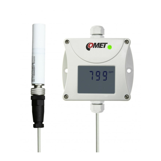
- Page 1 Instruction Manual T5140 T5141 T5145 Programmable transmitter of CO concentration with 4-20 mA output T5240 T5241 T5245 Programmable transmitter of CO concentration with 0-10 V output...
- Page 2 © Copyright: COMET SYSTEM, s.r.o. It is prohibited to copy and make any changes in this manual, without explicit agreement of company COMET SYSTEM, s.r.o. All rights reserved. COMET SYSTEM, s.r.o. makes constant development and improvement of their products. Manufacturer reserves the right to make technical changes to the device without previous notice.
-
Page 3: Table Of Contents
INFO MODE ....................8 ERROR STATES OF THE DEVICE ............9 TECHNICAL SUPPORT AND SERVICE ..........10 TECHNICAL DATA .................. 11 T5140 – AMBIENT AIR CO TRANSMITTER ........11 T5240 – AMBIENT AIR CO TRANSMITTER ......... 11 T5141 – CO TRANSMITTER WITH EXTERNAL PROBE ..... -
Page 4: General Description
General description The transmitters are designed for measurement of carbon dioxide concentration of air without aggressive ingredients. transmitter with 4 – 20 mA output T5140 ambient CO transmitter with 0 – 10 V output T5240 ambient CO transmitter with cable probe with 4 – 20 mA output T5141 transmitter with cable probe with 0 –... -
Page 5: Factory Settings
If special setting was not required in the order, the device is set from the manufacturer to the following parameters: 4 - 20 mA output: corresponds 0 to 2000 ppm (T5140 a T5145) corresponds 0 to 10 000 ppm (T5141) 0 - 10 V output:... -
Page 6: Device Installation
(see „Typical application wiring”). By jumper J1 select galvanically or non-galvanically isolated output (T5140, T5141 and T5145). Tighten the gland and screw the lid (check the integrity of the seal). The female connector for connecting TxxxxL transmitter connect according to the diagram at „Typical application... -
Page 7: Modification Of Device Adjustment
Modification of device adjustment Device adjustment is performed by means of the optional SP003 communication cable, connected to USB port of the PC. It is necessary to have installed configuration program Tsensor on the PC (program is free to download at www.cometsystem.com). During installation please take care about installation of driver for USB communication. -
Page 8: Info Mode
(e.g. screwdriver). Upper line of the LCD display shows value of CO concentration corresponding to output current 4 mA (output voltage 0 V) T5140, T5145 T5240, T5245 T5141 T5241 Press button again to get value of CO concentration corresponding to output current 20 mA (output voltage 10 V). -
Page 9: Error States Of The Device
Error states of the device Device continuously checks its state during operation. In case error is found LCD displays corresponding error code: Error 0 - first line displays „Err0“ (output current value is < 3.8 mA). Check sum error of stored setting inside device’s memory. This error appears if incorrect writing procedure to device’s memory occurred or if damage of calibration data appeared. -
Page 10: Technical Support And Service
Technical support and service Technical and service is provided by distributor. For contact see warranty certificate. discussion forum address www.forum.cometsystem.cz. IE-SNC-T51(2)XX-05... -
Page 11: Technical Data
Technical data T5140 – ambient air CO transmitter Output: 4 to 20 mA Power: 9 to 30 V dc Power consumption: 1 W during normal operation max. 4 W (for 50 ms with 15 s period) Output in case of error: <... -
Page 12: T5141 - Co Transmitter With External Probe
T5141 – CO transmitter with external probe Output: 4 to 20 mA Power: 9 to 30 V dc Power consumption: 1 W during normal operation max. 4 W (for 50 ms with 15 s period) Output in case of error: <... -
Page 13: T5145 - Co Duct Mount Transmitter
T5145 – CO duct mount transmitter Output: 4 to 20 mA Power: 9 to 30 V dc Power consumption: 1 W during normal operation max. 4 W (for 50 ms with 15 s period) Output in case of error: < 3.8 mA or > 24 mA Concentration of CO ±... -
Page 14: General
General Protection: IP30 T5140(L), T5240(L) IP65 (device with probe) T5141(L), T5241(L) IP20 T5145(L), T5245(L) Recommended interval of calibration: 5 year Working position: cable gland upwards T5140(L), T5240(L) any position T5141(L), T5241(L) any position *) T5145(L), T5245(L) _______________________________________________________________________________________________________________________________ *) The holes on the stem must be routed in the direction of the air flow, see chapter “Device installation”. -
Page 15: Operation Conditions
Operation conditions Operating temperature range of housing with electronics: -30 to +60 °C T5140(L), T5240(L), T5145(L), T5245(L) -30 to +80 °C T5141(L), T5241(L) It is recommended to switch off the LCD display at ambient temperatures above 70 °C. Operating temperature range of the measuring end of stem: -30 to +60 °C... -
Page 16: Dimensions
Dimensions T5140 T5240 T5140L T5240L IE-SNC-T51(2)XX-05... - Page 17 T5141 T5241 IE-SNC-T51(2)XX-05...
- Page 18 T5141L T5241L IE-SNC-T51(2)XX-05...
- Page 19 T5145 T5245 IE-SNC-T51(2)XX-05...
- Page 20 T5145L T5245L IE-SNC-T51(2)XX-05...
-
Page 21: Typical Application Wiring
Typical application wiring Device with 4-20 mA output can be connected to circuitry by means of galvanically isolated or galvanically non-isolated current loop. Output 0 - 10 V is galvanically non-isolated. Galvanically isolated 4 - 20 mA output transmitter with cable gland transmitter TxxxxL Loop resistance value Rc = R + resistance of wires shall fulfill the condition Rc[Ω] <... - Page 22 Galvanically non isolated 0 - 10 V output transmitter with cable gland transmitter TxxxxL R > 20 kΩ The value of the internal resistance (Ri) of the measuring instrument must be greater than 20 kΩ. IE-SNC-T51(2)XX-05...
-
Page 23: Optional Accessory
Optional accessory Mounting flange PP4 Mounting flange PP90 IE-SNC-T51(2)XX-05...
Need help?
Do you have a question about the T5140 and is the answer not in the manual?
Questions and answers