
Subscribe to Our Youtube Channel
Related Manuals for urmet domus 4203


Summary of Contents for urmet domus 4203
- Page 1 Mod. 4203 DS 4203-004A LBT 8786 INTERFACCIA GSM DOMUS CELL BASIC 2 GSM GATEWAY DOMUS CELL BASIC 2 Sch./Ref. 4203/11...
-
Page 2: Table Of Contents
Collegamento della linea telefonica ......................6 Collegamento dell’alimentatore ........................7 PROGRAMMAZIONE ............................. 7 Programmazione da telefono ........................7 Collegamenti per l’impiego dell’interfaccia Sch. 4203/50 ................9 INDICAZIONI OTTICHE ..........................10 TABELLA TONI ............................. 10 CARATTERISTICHE TECNICHE ........................11 LEGENDA SIMBOLI ............................. 11... -
Page 3: Note Informative
DICHIARAZIONE DI CONFORMITÀ UE SEMPLIFICATA Il fabbricante, URMET S.p.A., dichiara che il tipo di apparecchiatura radio: INTERFACCIA GSM DOMUS CELL BASIC 2 Sch. 4203/11 è conforme alla direttiva 2014/53/UE. Il testo completo della dichiarazione di conformità UE è disponibile al seguente indirizzo Internet: www.urmet.com... -
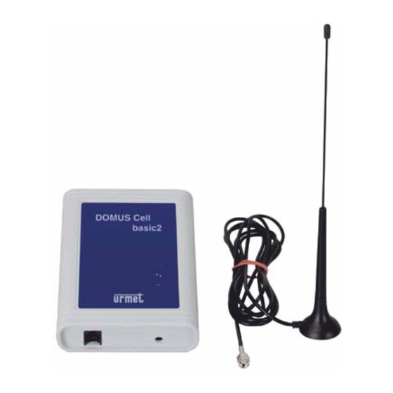
Page 4: Contenuto Della Confezione
CLI (Identifi cativo del chiamante) a standard FSK Bell • Blocco delle chiamate uscenti • Programmazione da telefono o PC con dispositivo di interfaccia opzionale Sch.4203/50 INSTALLAZIONE FISSAGGIO A MURO Scegliere la posizione maggiormente idonea per il fi ssaggio a muro avendo cura di posizionare l’antenna nel punto di maggiore campo, per verifi... -
Page 5: Collegamento Dell'antenna
COLLEGAMENTO DELL’ANTENNA Avvitare il connettore del cavo dell’antenna al connettore posto sulla parte superiore del DOMUS Cell basic. Si consiglia in ogni caso di seguire le seguenti indicazioni: • L’antenna deve essere collocata ad almeno 2 m di distanza da qualsiasi apparecchiatura elettronica presente nell’ambiente, ad almeno 15 cm da qualsiasi ostacolo, e in posizione tale da permettere una buona ricezione del campo radio. -
Page 6: Inserimento Della Sim-Card
INSERIMENTO DELLA SIM-CARD Il SIM-READER si trova posizionato nella parte superiore di DOMUS Cell basic. Inserire la SIM-CARD nel modulo GSM come indicato in fi gura. IMPORTANTE: IN CASO DI SOSTITUZIONE DELLA SIM-CARD CON DOMUS CELL BASIC GIÀ IN USO, È NECESSARIO SCOLLEGARE IL CAVO DI ALIMENTAZIONE E RICOLLEGARLO SOLAMENTE AD OPERAZIONE ULTIMATA. -
Page 7: Collegamento Dell'alimentatore
Il DOMUS Cell basic prevede una confi gurazione programmabile da utente in due diverse modalità: tramite telefono oppure tramite l’accessorio Sch. 4203/50 e l’applicativo GGset su PC. In fase iniziale il sistema è confi gurato, in seguito l’utente può variare tale confi gurazione secondo le proprie necessità e comunque può... - Page 8 Funzionalità Parametro Valore Default Password di accesso alla programmazione Se si dimentica la password, per tornare al codice 0 0 0 0 di fabbrica, occorre contattare l’area tecnica assistenza clienti. Prefi ssi/numeri abilitati (da 1 a 4 cifre iniziali) Per cancellare la programmazione non inserire nessuna cifra.
-
Page 9: Collegamenti Per L'impiego Dell'interfaccia Sch. 4203/50
Memorizzazione del PIN della SIM 1 2 3 4 Tutte le programmazioni sono memorizzate nella SIM-CARD pertanto, se questa viene sostituita, occorre ripetere le programmazioni. COLLEGAMENTI PER L’IMPIEGO DELL’INTERFACCIA Sch. 4203/50 Connesso verso DOMUS Cell Mini USB (al computer) Connesso verso telefono o PABX... -
Page 10: Indicazioni Ottiche
INDICAZIONI OTTICHE Acceso fi sso Rete di alimentazione presente Spento Linea telefonica libera Acceso fi sso Linea telefonica impegnata Lampeggiante Dispositivo collegato al PC Lampeggia 2 secondi / 2 secondi SIM non leggibile o assente Assenza di comunicazione tra modulo GSM e Lampeggia 2 secondi/breve spegnimento scheda CPU Da 1 a 5 brevi lampeggi / 4 secondi spento... -
Page 11: Caratteristiche Tecniche
CARATTERISTICHE TECNICHE Meccaniche: Dimensioni: ..................130 x 100 x 37 mm (escluso antenna) Peso: ......................170 g massimi (escluso adapter) Installazione: ...................A muro con tasselli ad espansione Contenitore: ............................Plastico Antenna: .............................. Esterna Connettore antenna: ......................... SMA femmina Ambientali: Temperatura di funzionamento: ....................-20 ÷ +50 °C Umidità: ..........................10 ÷... - Page 12 Connecting the telephone line ........................16 Connecting the power supply ........................17 PROGRAMMING ............................17 Programming using a telephone ......................17 Connections for use of the Ref. 4203/50 interface ................... 19 OPTICAL INDICATIONS ..........................20 TONE TABLE ..............................20 TECHNICAL SPECIFICATIONS ........................21 KEY TO SYMBOLS ............................
-
Page 13: Informative Notes
SIMPLIFIED EU DECLARATION OF CONFORMITY Hereby, URMET S.p.A. declares that the radio equipment types: GSM GATEWAY DOMUS CELL BASIC 2 Ref. 4203/11 is in compliance with Directive 2014/53/EU. The full text of the EU declaration of conformity is available at the following internet address: www.urmet.com... -
Page 14: Contents Of The Box
FSK Bell standard CLI (called ID) • Outbound call block • Programming via telephone or PC with optional interface device Ref. 4203/50 INSTALLATION WALL MOUNTING Choose the most suitable position for fi xing the device onto the wall. Position the antenna where the fi eld is strongest. -
Page 15: Connecting The Antenna
CONNECTING THE ANTENNA Screw the antenna cable connector into the connector on the upper part of DOMUS Cell basic. Important tips: • The antenna should be arranged at least 2 metres away from any electronic device in the area and at least 15 centimetres from any obstacle in a position allowing good radio fi... -
Page 16: Inserting The Sim Card
INSERTING THE SIM CARD The SIM reader is arranged on the upper part of DOMUS Cell basic. Insert the SIM card in the GSM module, as shown in the fi gure. IMPORTANT: TO REPLACE THE SIM CARD WHILE DOMUS CELL BASIC IS IN USE, DISCONNECT THE POWER CABLE AND RECONNECT IT ONLY AFTER COMPLETING THE OPERATION. -
Page 17: Connecting The Power Supply
The DOMUS Cell basic system can be programmed by the user in two different ways: via telephone or via Ref. 4203/50 accessory and GGset application on PC. The system must be initially confi gured, after which the confi guration may be changed by the user according to needs. It is always possible to revert to the original confi... - Page 18 Functions Parameter Value Default Programming access password Contact the Customer Service Technical Area 0 0 0 0 to restore the default code if you forget your password. Enabled area codes/numbers (from 1 to 4 initial digits) Leave blank to delete programming. Polarity inversion at beginning and end of a conversation.
-
Page 19: Connections For Use Of The Ref. 4203/50 Interface
1 2 3 4 All settings are stored on the SIM card. Therefore, the programming procedure will need to be repeated if the SIM card is replaced. CONNECTIONS FOR USE OF THE Ref. 4203/50 INTERFACE Connected to DOMUS Cell Mini USB (to computer) -
Page 20: Optical Indications
OPTICAL INDICATIONS On steady Powered Telephone line is free On steady Telephone line is engaged Blinking Device connected to PC Blinking 2 seconds/2 seconds SIM either unreadable or missing No communication between GSM module and Blinking 2 seconds/off briefl y CPU board From 1 to 5 short blinks/4 seconds off 1 = minimum fi... -
Page 21: Technical Specifications
TECHNICAL SPECIFICATIONS Mechanical: Dimensions: ..................130 x 100 x 37 mm (excluding antenna) Weight: ......................170 g max. (excluding adapter) Installation: ......................On wall, with anchor bolts Casing: ..............................Plastic Antenna: ............................. External Antenna connector: ........................SMA female Environmental conditions: Working temperature range:....................from -20 to +50 °C Humidity: ........................ - Page 22 ITALIANO DIRETTIVA 2012/19/UE DEL PARLAMENTO EUROPEO E DEL CONSIGLIO del 4 luglio 2012 sui rifi uti di apparecchiature elettriche ed elettroniche (RAEE) Il simbolo del cassonetto barrato riportato sull’apparecchiatura o sulla sua confezione indica che il prodotto alla fi ne della propria vita utile deve essere raccolto separatamente dagli altri rifi uti. L’utente dovrà, pertanto, conferire l’apparecchiatura giunta a fi...
- Page 23 DS4203-004A...
- Page 24 DS 4203-004A LBT 8786 URMET S.p.A. Area tecnica 10154 TORINO (ITALY) servizio clienti +39 011.23.39.810 VIA BOLOGNA 188/C http://www.urmet.com Telef. +39 011.24.00.000 (RIC. AUT.) e-mail: info@urmet.com +39 011.24.00.300 - 323 MADE IN CZECH REPUBLIC...
Need help?
Do you have a question about the 4203 and is the answer not in the manual?
Questions and answers