
Subscribe to Our Youtube Channel
Related Manuals for Olympus VISERA CLV-S40


Summary of Contents for Olympus VISERA CLV-S40
- Page 1 INSTRUCTIONS VISERA XENON LIGHT SOURCE CLV-S40 USA: CAUTION: Federal law restricts this device to sale by or on the order of a physician.
-
Page 3: Table Of Contents
Rear and side panels ..............Chapter 3 Installation and Connection ........Installation..................Connection to an endoscope ............Connection to an Olympus video system (OTV-S7V, etc.) ..... Connection to an AC mains power supply ........Chapter 4 Inspection ..............Turn the power ON ................. - Page 4 Contents Chapter 6 Lamp Replacement..........When to replace the lamp ............... Chapter 7 Care, Storage and Disposal ........Care ....................Storage ................... Disposal ..................Chapter 8 Troubleshooting ............Troubleshooting guide ..............Returning the light source for repair..........Appendix..................System chart .................... Operating environment................
-
Page 5: Labels And Symbols
Labels and Symbols Labels and Symbols Safety-related labels are attached to the instrument at the locations shown below. If labels are missing or illegible, contact Olympus. Front side Lamp rating Rear side Electrical rating plate Product name, rated voltage and serial number are described. - Page 6 Labels and Symbols Lamp rating Electrical rating plate Back cover of this instruction manual Manufacturer Authorized representative in the European Community VISERA XENON LIGHT SOURCE CLV-S40...
-
Page 7: Important Information - Please Read Before Use
Important Information — Please Read Before Use Intended use This instrument has been designed to be used with an Olympus endoscope, Video system, accessories and other ancillary equipment for observation, diagnosis and endoscopic treatment. Do not use this instrument for any purpose other than its intended use. -
Page 8: User Qualifications
Some problems that appear to be malfunctions may be correctable by referring to Chapter 8, “Troubleshooting”. If the problem cannot be resolved using the information in Chapter 8, contact Olympus. VISERA XENON LIGHT SOURCE CLV-S40... -
Page 9: Signal Words
Important Information — Please Read Before Use Signal words The following signal words are used throughout this manual: Indicates an imminently hazardous situation which, if not avoided, will result in death or serious injury. Indicates a potentially hazardous situation which, if not avoided, could result in death or serious injury. - Page 10 − Keep liquids away from all electrical equipment. If spilled fluids enter the unit, stop operation of the equipment at once and contact Olympus. − Do not prepare, inspect or use this instrument with wet hands. •...
- Page 11 Important Information — Please Read Before Use • Although the illumination light emitted from the endoscope’s distal end is required for endoscopic observation and treatment, it may also cause alteration of living tissues such as protein denaturation of liver tissue and perforation of the intestines by inappropriate using.
- Page 12 Important Information — Please Read Before Use • Xenon light sources produce significant heat due to the high intensity light required for endoscopic procedures. If the disconnected end of the light guide cable or the distal end of an endoscope touches operating room drapes or other flammable materials, fire can result.
- Page 13 Important Information — Please Read Before Use As defined by the international safety standard (IEC 60601-1), medical electrical equipment is classified into the following types: Type CF (the instrument can safely be applied to any part of the body, including the heart), and Type B/BF (the instrument can safely be applied to any organ except the heart).
-
Page 14: Chapter 1 Checking The Package Contents
Match all items in the package with the components shown below. Inspect each item for damage. If the instrument is damaged, a component is missing or you have any questions, do not use the instrument; immediately contact Olympus. Light source (CLV-S40) Foot holders (MD-512, 4 pcs.) - Page 15 Chapter 1 Checking the Package Contents VISERA XENON LIGHT SOURCE CLV-S40...
-
Page 16: Chapter 2 Instrument Nomenclature
Chapter 2 Instrument Nomenclature Chapter 2 Instrument Nomenclature Symbols and descriptions Output connector Connector for endoscope Power switch Power ON/OFF Lamp Main lamp (xenon) Emergency lamp (halogen) High intensity mode Brightness control Standby mode Manual control Automatic control Brightness Automatic/manual Min. VISERA XENON LIGHT SOURCE CLV-S40... - Page 17 Chapter 2 Instrument Nomenclature Lamp life meter Lamp life Others Alternating current Circuit breaker Equipotential terminal Refer to instructions Caution hot VISERA XENON LIGHT SOURCE CLV-S40...
-
Page 18: Front Panel
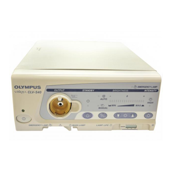
Chapter 2 Instrument Nomenclature Front panel 8. AUTO indicator 9. Brightness control indicator 7. MANUAL indicator 10. Brightness control switches 6. AUTO/MANUAL brightness selector 11. Emergency lamp indicator 5. Standby mode indicator 12. Brightness level indicator 4. Output connector 3. Connector cover 13. - Page 19 Chapter 2 Instrument Nomenclature 4. Output connector The connector transmits light to the connected endoscope or light guide cable. 5. Standby mode indicator The indicator lights when the standby mode is selected. 6. AUTO/MANUAL brightness selector Press to select AUTO or MANUAL brightness control. 7.
-
Page 20: Rear And Side Panels
Chapter 2 Instrument Nomenclature Rear and side panels 1. VIDEO IN connector 4. AC inlet 2. SYSTEM connector 3. VIDEO OUT connector CSA mark 7. Equipotential Rating plate terminal 5. Circuit breakers 6. LIGHT CONT. connector VISERA XENON LIGHT SOURCE CLV-S40... - Page 21 Chapter 2 Instrument Nomenclature Air vents Side bumpers Right side Air vents 8. Lamp access cover 9. Cover Power cord 10. Side bumpers Left side (viewed from rear) VISERA XENON LIGHT SOURCE CLV-S40...
- Page 22 6. LIGHT CONT. connector The connector is used for automatic brightness control when connected to an Olympus OTV-S5, OTV-S6, OTV-S7V, OTV-SX or OTV-SX2 video system. 7. Equipotential terminal In the case of equipotential, connect this terminal to a potential equalization busbar of the electrical installation.
-
Page 23: Chapter 3 Installation And Connection
Install and connect all equipment described as follows: Installation • Do not place any equipment other than the Olympus video system on the top of the light source. Otherwise, equipment damage can result. • The light source’s air vents should be clear of ancillary equipment. - Page 24 Chapter 3 Installation and Connection Preparation of the lamp life meter Be sure to remove the orange tape. If the tape is attached, the lamp life meter will not work (see Figure 3.1). Tape lamp life meter Figure 3.1 VISERA XENON LIGHT SOURCE CLV-S40...
- Page 25 Chapter 3 Installation and Connection Preparation of the connector cover holder When using a fiberscope (BF TYPE 40 series/CHF TYPE 20 series), attach the provided connector cover holder to this instrument (see Figures 3.2 and 3.3). • Pull out the cover from the side panel of this instrument. •...
- Page 26 Chapter 3 Installation and Connection Removal of the connector cover holder If the connector cover holder is not needed, it can be removed from this instrument (see Figure 3.5). • Pull out the connector cover holder with picking 2 portions. Picking points Figure 3.4 Figure 3.5...
-
Page 27: Connection To An Endoscope
Chapter 3 Installation and Connection Connection to an endoscope • Use compatible endoscope only. Using incompatible endoscope can result in patient injury and/or equipment damage. Refer to the “System chart” in the Appendix for compatible endoscope of this instrument. • If the surface of the endoscope is dirty, reprocess it according to the directions given in the endoscope’s instruction or reprocessing manual before connecting it to the light source. - Page 28 Chapter 3 Installation and Connection Connect the light guide cable to the rigid endoscope. Insert the light guide connector into the output connector on the front panel of the light source until it stops (see Figure 3.7). Figure 3.7 The following light guide cables are compatible with the high intensity mode: A3290/91/92/93/94/95/96/97/98 Connection to a videoscope...
- Page 29 Chapter 3 Installation and Connection The following videoscopes are compatible with the high intensity mode: LTF TYPE V/V2/V3 A4941A/43A A4801A/03A/05A A50001A/03A/21A/23A Connection to a fiberscope (with rigid endoscope type light guide connector) Insert the light guide connector into the output connector on the front panel of the light source until it stops (see Figure 3.9).
- Page 30 Chapter 3 Installation and Connection Connection to a fiber scope (BF TYPE 40 series/CHF TYPE 20 series) Lift the connector cover locking hook upward, then pull it toward you to remove the connector cover (see Figure 3.10). Figure 3.10 Hook the removed connector cover on the connector cover holder on the light source’s side panel (see Figures 3.11 and 3.12).
- Page 31 Chapter 3 Installation and Connection Figure 3.12 Insert the light guide connector into the output connector on the front panel of the light source until it stops (see Figure 3.13). Figure 3.13 VISERA XENON LIGHT SOURCE CLV-S40...
- Page 32 Chapter 3 Installation and Connection To reattach the removed connector, use the following steps: • Unhook the connector cover from the connector cover holder. • Fit the positioning claw on the top of the connector cover into the groove on the output connector (see Figure 3.14). Positioning claw Figure 3.14 •...
-
Page 33: Connection To An Olympus Video System (Otv-S7V, Etc.)
Chapter 3 Installation and Connection Connection to an Olympus video system (OTV-S7V, etc.) To view the endoscopic image on a TV monitor, prepare an Olympus video system, such as the OTV-S7V. Connect the light control cable supplied with the Olympus video system to the LIGHT CONT. - Page 34 To avoid damaging electrical contacts and/or causing a malfunction, do not apply excessive force to any connector. • In combination with some non-Olympus video system, the automatic brightness control may not operate properly, and endoscopic observation and treatment may be impossible.
-
Page 35: Connection To An Ac Mains Power Supply
Chapter 3 Installation and Connection Connection to an AC mains power supply Connect the power cord directly to a wall mains outlet. If the light source is not properly grounded, electric shock and/or fire can result. • Do not allow the power cord to become wet. A wet power cord may cause electrical shock. - Page 36 Chapter 3 Installation and Connection Connect the power cord to the inlet on the rear panel of the light source and connect the power plug to a wall mains outlet (see Figure 3.18). Wall mains outlet Power plug Figure 3.18 VISERA XENON LIGHT SOURCE CLV-S40...
-
Page 37: Chapter 4 Inspection
Chapter 8, “Troubleshooting”. If the irregularity is still suspected after consulting Chapter 8, contact Olympus. Damage or irregularity may compromise the patient’s or user’s safety and may result in more severe equipment damage. - Page 38 Confirm the circuit breakers. If the breakers are not popped out, turn the light source OFF. Do not use the light source and immediately contact Olympus. If the breakers have tripped (popped out), reset them according to steps 4. and 5..
- Page 39 Chapter 4 Inspection When a circuit breaker trips, do not reset it immediately. Turn the light source OFF and wait at least 15 seconds before resetting the circuit breakers to prevent damaging them. Turn the light source OFF, disconnect the power cord from the wall mains outlet and depress both the circuit breakers until they click (see Figure 4.3).
-
Page 40: Checking The Lamp Life
If the indicator reaches over 500h, replace the lamp with a new one as described in Chapter 6, “Lamp Replacement”. Replace an expired lamp with a new one as soon as possible. An expired lamp may explode or go out during use. If a lamp explosion occurred, contact Olympus. VISERA XENON LIGHT SOURCE CLV-S40... -
Page 41: Inspection Of Illumination
Chapter 4 Inspection • Be sure to remove the orange tape from the lamp life meter (see Figure 3.1 on page 20). If the tape is attached, the lamp life meter will not work. • The lamp life meter is not active when the light source is OFF. - Page 42 Chapter 4 Inspection • Make sure that the indicator of the lamp life meter is blinking constantly. If it is not, contact Olympus. • For details on opening and closing the lamp access cover and replacing the lamp, see Chapter 6, “Lamp Replacement”.
-
Page 43: Inspection Of The Light Cutoff Function
• If you observe conspicuous light emission from the output connector after disconnecting the endoscope, stop using the light source and contact Olympus. Confirm that no light is emitted from the light source by following the procedures described below. While emitting light from the endoscope, disconnect the endoscope. Place a piece of paper over the output connector of the light source and confirm that no light is being emitted from it (see Figure 4.6). -
Page 44: Inspection Of The Standby Mode
Chapter 4 Inspection Inspection of the standby mode The standby mode is intended to temporarily stop/suspend light output from the light source. Use this mode when replacing the scope or temporarily suspending its use. Press the AUTO/MANUAL brightness selector to engage the manual brightness control. -
Page 45: Inspection Of The High Intensity Mode
Chapter 4 Inspection Inspection of the high intensity mode Inspect the high intensity mode by following the procedures described below: Press the AUTO/MANUAL brightness selector to engage the manual brightness control mode (see Figure 4.8). Press the brightness control switches to set the brightness level to 0. Connect an endoscope compatible with high intensity mode to the output connector on the light source. -
Page 46: Inspection Of Brightness Adjustment
Chapter 4 Inspection If the high intensity mode indicator does not go off after the endoscope is disconnected, immediately stop using the light source and contact Olympus. • The following endoscopes and light guide cables are compatible with the high intensity mode: −... - Page 47 Chapter 4 Inspection • When using the automatic brightness control function with the following products, brightness adjustment by the brightness control switches is not available. In this case, set the brightness level to “0”. For the exposure control, refer to the instruction manual of the following products.
- Page 48 Chapter 4 Inspection When switching the normal intensity mode to high intensity mode, be sure to set the brightness level to below 0. Otherwise, the brightness will exceed the necessary level. It may result operator and/or patient injury. Make sure that the manual indicator is lit. Confirm that the following occurs when the brightness control switches are pressed (see Figure 4.10): •...
- Page 49 Otherwise, the brightness will exceed the necessary level, and operator and/or patient injury may result. • In combination with some non-Olympus video system, the automatic brightness control may not operate properly, and endoscopic observation and treatment may be impossible. VISERA XENON LIGHT SOURCE CLV-S40...
- Page 50 Chapter 4 Inspection • When this instrument and the VISERA video system center OTV-S7V are combined with any of the following products, the brightness control indicator and MANUAL indicator are disabled, and it is not possible to control the brightness from this instrument.
- Page 51 Chapter 4 Inspection Confirm that the following occurs when the distance between the distal end of the endoscope and an object is varied between 5 and 60 mm (see Figure 4.12): As the distance is increased, the light being emitted from the distal end of the endoscope increases.
- Page 52 Chapter 4 Inspection • Once “MAX” has been reached, pressing the switch will not cause any further change. • Once “MIN” has been reached, pressing the switch will not cause any further change. • If the endoscope is not connected, the LED indicators will still change as described above, but the intensity of light emitted from the output connector will change only slightly.
-
Page 53: Emergency Lamp
In this case, immediately stop using the instrument and contact Olympus. Move the emergency lamp switch lever from the main lamp to the emergency lamp position while the main lamp is illuminated; the main lamp will go out and the emergency lamp will light. -
Page 54: Chapter 5 Operation
“Troubleshooting guide”. If an abnormality is still suspected, stop using the instrument on patients again and contact Olympus as described in Section 8.2, “Returning the light source for repair”. − If the image on the monitor becomes white or black when the automatic brightness control is selected, the automatic brightness control may be malfunctioning. - Page 55 Chapter 5 Operation − If another abnormality occurs or is suspected, connect the endoscope to the prepared another light source, after treatment to secure a safety of the patient. After withdrawal of the endoscope from the patient, proceed according to the instructions in Chapter 8, “Troubleshooting”.
-
Page 56: Recommended Video Systems And Functions
Recommended video systems and functions Recommendable functions Video system Automatic brightness Manual brightness High intensity mode control control Olympus video system (OTV-S5C, OTV-S6C, OTV-S7V, × OTV-SX, OTV-SX2C) with light control cable × × Video system with BNC cable Video system without BNC ×... -
Page 57: Power Supply And Igniting The Lamp
Chapter 5 Operation − Fiberscope CHF TYPE CB30L/S, URF TYPE P3 − Videoscope LTF TYPE V/V2/V3, A4941A/43A, A4801A/03A/05A, A50001A/03A/21A/23A • This instrument includes a memory function for the intensity mode, which stores the intensity setting being used when the light source is turned OFF. Therefore, the user may start the next operation with the same setting used when the light source was turned OFF. -
Page 58: Adjusting The Brightness (Automatic/Manual)
Chapter 5 Operation Adjusting the brightness (automatic/manual) If the endoscopic image dims during use, this may be a sign that blood or mucus is adhered to the light guide on the endoscope’s distal end. Remove the blood or mucus in order to obtain optimum illumination and to ensure the safety of examination. - Page 59 Chapter 5 Operation • When this instrument and the VISERA video system center OTV-S7V are combined with any of the following products, the brightness control indicator and MANUAL indicator are disabled, and it is not possible to control the brightness from this instrument.
- Page 60 Pressing a brightness control switches once moves the level one step; holding the switch down moves the level continuously. In combination with some non-Olympus video system, the automatic brightness control may not operate properly, and endoscopic observation and treatment may be impossible.
- Page 61 Chapter 5 Operation Brightness level indicators Illuminated Brightness control switches Figure 5.3 Pressing a brightness control switch once moves the level one step; holding the switch down moves the level continuously. VISERA XENON LIGHT SOURCE CLV-S40...
-
Page 62: After Use
Chapter 5 Operation After use Do not bring the distal end of a fiberscope, videoscope, rigid scope or light guide cable in contact with a human body or a flammable object such as an operating room drape. Otherwise, the light may cause burns to the body or burn the flammable object. -
Page 63: Chapter 6 Lamp Replacement
Fire and/or equipment damage can result. • Never use a lamp that has not been approved by Olympus. The use of a non-approved lamp can cause damage to the light source and ancillary equipment, malfunction and/or fire. -
Page 64: When To Replace The Lamp
If the wrench falls inside the light source, immediately turn the light source OFF, disconnect the power cord and contact Olympus. If the light source is used while the wrench is detached inside it, electric shock can result. - Page 65 Chapter 6 Lamp Replacement Lamp cover knob (a) Lock mark Lamp access cover Figure 6.2 Clamping knob (b) Lamp access cover Clamping knob (d) Hexagon wrench Clamping knob (c) Figure 6.3 After allowing sufficient time for the lamp and heat sinks (a) and (b) to cool, loosen clamping knob (b) (front panel side) by turning it counterclockwise.
- Page 66 Chapter 6 Lamp Replacement Disengage the clamp on heat sink (a) and pull out the lamp (see Figure 6.4). Using a clean lint-free cloth, wipe off any residual heat compound from the heat sink. Remove the new lamp from its container. With a finger, apply the supplied heat compound (for better heat conduction) evenly and thickly on the area indicated by hatched lines on the “–”...
- Page 67 Chapter 6 Lamp Replacement Confirm that the surfaces of heat sinks (a) and (b) are parallel, then tighten the clamp on heat sink (a) (see Figure 6.6). Insert this assembly into the lamp housing fitting the guide pin into the guide pin hole of heat sink (b), then securely tighten clamping knobs (c) and (d), in that order (see Figure 6.7).
- Page 68 Chapter 6 Lamp Replacement Put the hexagon wrench back into the lamp access cover. Close the lamp access cover and turn the lamp cover knob (a) all the way to the lock mark position. The light source will not function unless the cover is closed tightly and the lamp cover knob (a) is turned to the lock mark position (see Figure 6.8).
-
Page 69: Chapter 7 Care, Storage And Disposal
Chapter 7 Care, Storage and Disposal Chapter 7 Care, Storage and Disposal Care • Use only a dry lint-free cloth to clean the power switch. Do not moisten the lint-free cloth; the switch could fail or electric shock may result. •... -
Page 70: Storage
Chapter 7 Care, Storage and Disposal Storage Do not store the light source, lamp(s) or power cord in any of the locations listed below. Damage to the equipment may result: − Places exposed to high temperatures, high humidity, or liquids. −... -
Page 71: Chapter 8 Troubleshooting
Some problems that appear to be malfunctions may be correctable by referring to Section 8.1, “Troubleshooting guide”. If the problem cannot be resolved by described remedial action, stop using the instrument and send it to Olympus for repair. Olympus does not repair accessory parts. If an accessory part becomes damaged, contact Olympus to purchase a replacement. - Page 72 Chapter 8 Troubleshooting Irregularity Possible cause Solution description Lamp does not Power cord is not connected. Connect power cord. light. The light source is not turned Turn the light source ON. Circuit breaker(s) has tripped. Reset circuit breaker(s). Lamp access cover is not Close the lamp access cover tightly closed.
- Page 73 Chapter 8 Troubleshooting Irregularity Possible cause Solution description Endoscope A designated fiberscope, rigid Connect a designated fiberscope, cannot be scope or videoscope is not rigid scope or videoscope. connected to being used. CLV-S40. Field of view is Brightness control switch Adjust as required.
- Page 74 Chapter 8 Troubleshooting Front panel and display Irregularity Possible cause Solution description Panel settings The light source is not turned Turn the light source ON. cannot be made. Circuit breaker(s) has tripped. Reset circuit breaker(s). Lamp access cover is not Close the lamp access cover tightly closed.
-
Page 75: Returning The Light Source For Repair
Olympus is not liable for any injury or damage which occurs as a result of repairs attempted by non-Olympus personnel. Before returning the light source for repair contact Olympus. With the CLV-S40 include a description of the malfunction or damage and the name and telephone number of the individual at your location who is most familiar with the problem. -
Page 76: Appendix
New products released after the introduction of this instrument may also be compatible for use in combination with this instrument. For further details, contact Olympus. If combinations of equipment other than those shown below are used, the full responsibility is assumed by the medical treatment facility. - Page 77 Appendix VISERA video system center (OTV-S7V) Light control cable (MAJ-944) Endoscopic video OES 3CCD video system monitor (OTV-SX2) (OEV series) Light control cable (MAJ-439) OES video system (OTV-SX) Light control cable (MB-608) OES video system (OTV-S5) Light control cable (MH-988) OES video system (OTV-S6) Light control cable...
-
Page 78: Operating Environment
Appendix Operating environment Operating Ambient temperature 10 – 40°C (50 – 104°F) environment Relative humidity 30 – 85% Air pressure 700 – 1060 hPa (0.7 – 1.1 kgf/cm (10.2 – 15.4 psia) Transportation and storage environment Transportation and Ambient temperature –25 to +70°C storage environment (–13 to +158°F) Relative humidity... - Page 79 Appendix Item Specification Illumination Lamp Xenon short-arc lamp (ozone-free) 300 W Lamp life Approx. 500 hours of continuous ∗1 Ignition Switching regulator Brightness Light-path diaphragm control adjustment Cooling Forced-air cooling Emergency lamp Halogen lamp (without mirror) 24 V 150 W Emergency lamp life Approx.
- Page 81 ©2002 OLYMPUS MEDICAL SYSTEMS CORP. All rights reserved. No part of this publication may be reproduced or distributed without the express written permission of OLYMPUS MEDICAL SYSTEMS CORP. OLYMPUS is a registered trademark of OLYMPUS CORPORATION. Trademarks, product names, logos, or trade names used in this document are generally registered trademarks or trademarks of each company.
- Page 82 Manufactured by 2951 Ishikawa-cho, Hachioji-shi, Tokyo 192-8507, Japan Fax: (042)646-2429 Telephone: (042)642-2111 Distributed by 3500 Corporate Parkway, P.O. Box 610 Center Valley, PA 18034-0610, U.S.A. Fax: (484)896-7128 Telephone: (484)896-5000 5301 Blue Lagoon Drive, Suite 290 Miami, FL 33126-2097, U.S.A. Fax: (305)261-4421 Telephone: (305)266-2332 (Premises/Goods delivery) Wendenstrasse 14-18, 20097 Hamburg, Germany (Letters) Postfach 10 49 08, 20034 Hamburg, Germany Telephone: (040)237730 KeyMed House, Stock Road, Southend-on-Sea, Essex SS2 5QH, United Kingdom...
Need help?
Do you have a question about the VISERA CLV-S40 and is the answer not in the manual?
Questions and answers