Table of Contents
Advertisement
NEW BRUNSWICK SCIENTIFIC CO., INC.
BOX 4005 . 44 TALMADGE ROAD . EDISON, NJ 08818-4005 . 732-287-1200
TELEPHONE: 800-631-5417 . FAX: 732-287-4222 . TELEX: 4753012 NBSCO
INTERNET: http://www.nbsc.com/ . E-MAIL: bioinfo@nbsc.com
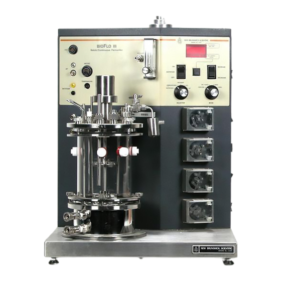
BIOFLO III
THE MICROPROCESSOR
CONTROLLED
LABORATORY-SCALE
FERMENTOR
MANUAL NO.: M1226-0050/N
Advertisement
Table of Contents

Subscribe to Our Youtube Channel
Related Manuals for NEW BRUNSWICK SCIENTIFIC BIOFLO III


Summary of Contents for NEW BRUNSWICK SCIENTIFIC BIOFLO III
- Page 1 BIOFLO III THE MICROPROCESSOR CONTROLLED LABORATORY-SCALE FERMENTOR MANUAL NO.: M1226-0050/N NEW BRUNSWICK SCIENTIFIC CO., INC. BOX 4005 . 44 TALMADGE ROAD . EDISON, NJ 08818-4005 . 732-287-1200 TELEPHONE: 800-631-5417 . FAX: 732-287-4222 . TELEX: 4753012 NBSCO INTERNET: http://www.nbsc.com/ . E-MAIL: bioinfo@nbsc.com...
- Page 3 NBS factory without prior authorization from New Brunswick Scientific Co., Inc.. In addition to the above, all biological shakers shipped to the U.S.A. and Canada carry an additional one-year...
- Page 4 IMPORTANT NOTICE: RETURN MATERIAL AUTHORIZATION POLICY IF SERVICE IS REQUIRED: PLEASE CALL OUR SERVICE DEPARTMENT AT 1-800-237-2298 PLEASE DO NOT RETURN ANY EQUIPMENT FOR SERVICE WITHOUT A RETURN AUTHORIZATION AND NUMBER WHICH CAN BE OBTAINED FROM OUR SERVICE DEPARTMENT. THE RETURN AUTHORIZATION NUMBER MUST APPEAR ON THE OUTSIDE OF ALL CARTONS.
-
Page 5: Table Of Contents
1.11 Exhaust System 1.12 Sampling System 1.13 Flowmeter CHAPTER 2: INSTALLATION Inspection Description of the BioFlo III Console Installation of Console Service Connections Recorder Connections CHAPTER 3: PREPARATION AND OPERATION Cleaning of Vessel Vessel Assembly Preparation Before Sterilization Sterilization Procedure... - Page 6 Electrostatic Device (ESD) Warning ESD Precautions APPENDICES BioFlo III Operational Tips Communication Protocols for NBS RS-232/422 DRAWING LIST...
-
Page 8: Chapter 1: Introduction
P.O. Box 4005, Edison, New Jersey 08818-4005, USA. DESCRIPTION OF EQUIPMENT BioFlo III is a versatile bioreactor that provides a fully equipped state of the art fermentation system in one compact package. BioFlo III can be employed for batch or continuous culture with microprocessor control of pH, DO, agitation, temperature, nutrient feed, and electronic foam control. - Page 9 M1226-0050...
-
Page 10: Aeration
AERATION Sterile air is introduced into the medium through the ring sparger, and is controlled by the needle valve of the flowmeter. It is able to provide 1.5 (working volume) of sterile air thru 0.2 μm replaceable cartridge filter (Fig. 1). The filter is sterilizable with the vessel. -
Page 11: 1.13 Flowmeter
A 25mL screw-cap container serves as a reservoir (Fig. 2). 1.13 FLOWMETER The flowmeter is a simple, precise means of indicating flow rates in fluid systems. Their design is based on a variable area principle. BioFlo III is equipped with a 0.2 to 4.0 SLPM flowmeter. NOTE: 5L Unit uses an interchangeable tube to allow increased flow to 7.5 SLPM. -
Page 12: Chapter 2: Installation
CHAPTER 2 INSTALLATION INSPECTION Unpack the BioFlo III and carefully inspect for any apparent damage which may have occurred during transit. Report any obvious damage to the carrier and to New Brunswick Scientific Co., Inc.. Verify that the cabinet, its accessory kit (M1151-0010) and manual are correct. - Page 13 • 9 pin D-connector for recorder output. • 25 pin D-connector RS232/422. Right Hand Side of the Console • Switch panel (Fig. 6). The switch panel located on the right-hand side of the console includes: the Main Power Switch which controls the power to the system; the Prime Switch which fills the recirculation system with water before normal operation, and after each autoclaving.
-
Page 14: Installation Of Console
INSTALLATION OF CONSOLE Position the BioFlo III console on a firm and level surface in an area where services are readily available. Level the horizontal surface of the base with four leveling glides if necessary. Set the power and agitation switches to their off position. -
Page 15: Chapter 3: Preparation And Operation
CHAPTER 3 PREPARATION AND OPERATION CLEANING OF VESSEL Fill the vessel with a mild detergent and water solution. Let stand for one hour then scour thoroughly. Use a brush on both inside and outside surfaces. Drain the vessel and rinse several times with tap water. Repeat rinsing with distilled water and let dry. -
Page 16: Preparation Before Sterilization
before inserting into the port in the headplate.**** Insert exhaust condenser into the exhaust condenser port. Connect the exhaust filter on the top of the condenser with flexible tubing (Fig. 20). Slide 2" long, 1/4" inside diameter silicone tubing on the top of the sparger tube, then connect air filter to it (Fig. -
Page 17: Sterilization Procedure
Connect drain line to the rear of the cabinet. Connect air line to the rear of the cabinet. Adjust air pressure to 10 PSIG max. Connect the quick connects of plastic water lines to the vessel base and the exhaust condenser. As soon as the power switch is turned ON, press the prime switch ON and hold for approximately 10 seconds or until water runs out the drain line at the rear of the unit. -
Page 18: Ph Probe Preparation
Immediately crimp the foil and close off the vent tubing to maintain sterility. pH PROBE PREPARATION Inspect probe for possible shipping damage. If damage is observed notify the Service Department of the New Brunswick Scientific Co., immediately. M1226-0050... - Page 19 Check the level of the reference electrolyte. It should be about 1cm below the filling orifice, which is closed with a rubber T stopper. To add reference electrolyte, take the filling pipette (P0740-4820) and fill it with Viscolyte B (P0860-0130) Electrolyte. NOTE: The two chambers are filled with same Reference Electrolyte.
-
Page 20: Dissolved Oxygen Probe Calibration
DISSOLVED OXYGEN PROBE CALIBRATION Probe is to be calibrated after autoclaving vessel. There are two methods of obtaining zero on DO. METHOD 1 (Less Accurate) Remove the DO probe cable from the DO probe. Set the selector switch to "DO". Set the mode switch to "ZERO". -
Page 21: Preparation For Operation
3.65 7.32 PREPARATION FOR OPERATION Position the vessel on BioFlo III console. Connect the vessel base and the exhaust condenser with water lines.* Carefully place the DC motor on the vessel assembly. Add glycerin to the thermowell and insert (RTD) temperature probe. -
Page 22: Sampling Procedure
NOTE: Aeration is required whenever the agitation setpoint is greater than rpm. NBS suggests a minimum airflow rate of 0.25 vvm when running at speeds of 750 rpm or more. *NOTE: Always connect the water out line first. 3.10 D.O. ACTIVE SYSTEM The system is designed to control D.O. -
Page 23: Shut-Down Procedure
Remove bottle with sample from the sampler. Place the cap from a new bottle onto the bottle containing sample and install the new bottle in the sampler and make sure that the sample bottle is firmly sealed against the sampler gasket. Use aseptic techniques. -
Page 24: Chapter 4: Maintenance
CHAPTER 4 MAINTENANCE GENERAL Preventive maintenance is performed to keep equipment in proper working condition. When periodically performed, it will result in longer life for the equipment and reduce time lost due to equipment failure. CONSOLE CLEANING At least once a month, clean all metal parts of unit. Use a damp cloth moistened with water or mild detergent. -
Page 25: Replacement Part List
REPLACEMENT PART LIST Vessel (1.25L) Assy. M1226-2000 Vessel (2.5L) Assy. M1226-2003 Vessel (5L) Assy. M1226-2005 Inlet Filter P0200-0491 (37mm disc) Exhaust Filter P0200-0490 (50mm disc) RTD Assy. M1169-8002 pH Probe (1.25L, 2.5L) Liquid P0720-5325 pH Probe (1.25L, 2.5L) Gel, Ingold P0720-5582 pH Probe (1.25L) Gel, Broadley James P0720-5731... - Page 26 Bearing Housing Cover M1151-9444 Bearing Housing Cover O-Ring P0280-6093 Motor Assembly (1.25L, 2.5L) M1226-0700 Motor Assembly (5L) M1226-0800 Units shipped before April 1, 1996 (Mfg. No. M1226-3004, -3005, -3006) Heater, 400W, 100/120V Units P0620-1330 S.S.R. (240D10), 10 Amp, 100-240 VAC Unit P0400-3011 Heater, 400W, 220/240V Units P0620-1331...
- Page 27 APPENDIX I BIOFLO III OPERATION TIPS GLASS VESSEL ASSEMBLY Recommendations for prevention of cracking glass during assembly and autoclaving: • Cracking of glass due to overtightening of assembly screws will occur during tightening, not during autoclaving. Therefore, Prior to autoclaving, tighten screws "finger tight". If a wrench is applied at this point, turn each nut 1/2 revolution not to exceed 1 revolution.
- Page 28 NOTE: Fifty generations of recombinant E. coli have been propagated by BioFlo III in continuous culture. Prolonged operation as a chemostat requires double filters. OPERATION AS A CHEMOSTAT, SUGGESTIONS Switch the relative positions of the antifoam and acid pumps on the console so that the antifoam pump is now on the bottom and the acid pump is on the top.
- Page 29 FACTORS AFFECTING CONTROL The BioFlo III, BioFlo IV, BioFlo 3000, CelliGen Plus, MP40 and 80 controls most functions using a PI (Proportional & Integral), control algorithm. The proportional term of this algorithm is straight forward and provides a larger output for a greater error (set point minus current value).
- Page 30 addition. If the system is overshooting the set point in either direction the system could be made to control better by diluting the appropriate reagent (acid if undershooting and base if overshooting). The last factor that can be controlled is the amount added over a given period of time. Since in this system the pump is a fixed speed pump and the "ON"...
- Page 31 The temperature control loop might not control well in very vicious applications because the heat transfer rate was decreased so much the controller loses its ability to adjust the heating and cooling times properly. Most times this can be cured or improved by increasing the agitation and/or airflow rates and thus improving the heat transfer.
- Page 32 APPENDIX II COMMUNICATION PROTOCOLS FOR NBS RS232/422 COMMUNICATIONS The fermentor system has serial communications signals compatible with both the RS232C and RS422 standards which allow a host computer to be interfaced directly to the fermentor system. These signals are accessed via the 25 pin "D" connector (serial port).
- Page 33 UNIT NUMBER The multi-drop mode requires a unique unit number assignment for each fermentor in the multi-drop chain. All inquiries and directives and their responses in the multi-drop mode are prefixed with the unit number. The unit number is formatted as a single hexadecimal byte where the low-order nibble (bits 3-0) is set to a number between 0 and 15 and the high-order nibble (bits 7-4) is set to 8.
- Page 34 Inquiries are acknowledged by the requested report in the format described below. If parity is selected and a parity failure occurs, no response is made. REPORT FORMAT Each report begins with an identifying header (9 characters) followed by a space. The identifier for each report is as shown in Table 3.
- Page 35 TABLE 1 SETTINGS OF SWITCH 1 (S1) ON THE CONTROL BOARD S1-2 and S1-1 are used for setting baud rate: Baud Rate S1-2 S1-1 1200 2400 4800 9600 S1-3 is used for setting parity check: Parity S1-3 even S1-4 is used for setting mode: Mode S1-4 multidrop...
- Page 36 TABLE 2 SERIAL DATA FORMAT DATA FLOW ______________________________________________________________ star data data data data data stop stop _______________________________________________________________________ Mode and Parity bit 7 bit 8 __________________________________________________ multidrop, parity adata * parity bit __________________________________________________ multidrop, no parity adata * __________________________________________________ non-multidrop, parity parity bit __________________________________________________ non-multidrop, no parity...
- Page 37 M1226-0050...
- Page 38 TABLE 4 SERIAL INTERFACE CONNECTOR PIN # SIGNAL COMMENTS RS232 Data Output from Fermentor RS232 Data Input to Fermentor Ground Reference for all Signal IRXD+ RS422 Paired Data Input IRXD- to Fermentor ITXD+ RS422 Paired Data Output ITXD- from Fermentor 14-19 Open Selects RS232;...
- Page 39 TABLE 5 HEXADECIMAL CODES MULTIDROP UNIT NUMBERS Unit Number Hexadecimal Code M1226-0050...
- Page 40 M1226-0050...
- Page 41 PARTS LIST - 1 1/4L, 2 1/2L AND 5L BIOFLO III (Refer to Fig. 27A, 27B, 27C & 27D) ITEM PART NUMBER DESCRIPTION QTY. P0160-6450 Half Coupling P0160-6450 Half Coupling P0160-6451 Half Coupling M1151-4100 Bearing Housing Assy. M1152-4100 Bearing Housing Assy.
- Page 42 M1151-9226 Baffle M1152-9207 Baffle M1155-9205 Baffle M1151-9224 Impeller M1152-9208 Impeller M1155-9205 Impeller * 18 M1151-9518 Plug, Glass Vessel * 19 M1151-9520 Nut, Hose Connector * 20 M1151-9419 Seal, Hose Connector M1151-9227 Sparger Tube M1152-9407 Sparger Tube M1155-9203 Sparger Tube M1226-9434 Collar Nut M1151-9512 Collar Nut...
- Page 43 M1151-940P Harvest Tube M1152-9405 Harvest Tube M1155-9416 Harvest Tube M1132-9252 Well Thermister M1132-9254 Well Thermister M1132-9253 Well Thermister * 50 P0280-5362 O-Ring * 56 P0240-8270 * 57 P0240-7970 Ferrule * 58 P0240-8260 * 59 P0240-7960 Ferrule * 60 P0240-8240 * 61 P0240-7940 Ferrule * 62...
- Page 44 VESSEL SPARE PARTS 1.25L (M1226-0100) PART NO. DESCRIPTION WHERE USED P0280-5322 O-Ring 2-010 EPRP For knob assy., 3 per headplate, 3 for ¼” ports M1016-0890 Washer, D.O. Probe Used with probe adapter for 12mm probe P0280-5912 O-Ring 2-111 EPRP On pH port (on top and bottom) P0280-5292 O-Ring 2-007 EPRP When foam probe used...
- Page 45 VESSEL SPARE PARTS 2.5L (M1226-0101) PART NO. DESCRIPTION WHERE USED P0280-5322 O-Ring 2-010 EPRP For knob assy., 4 per headplate, 3 for ¼” ports M1016-0890 Washer, D.O. Probe Used with probe adapter for 12mm probe P0280-5912 O-Ring 2-111 EPRP On pH port (on top and bottom) P0280-5292 O-Ring 2-007 EPRP When foam probe used...
- Page 46 VESSEL SPARE PARTS 5L (M1226-0102) PART NO. DESCRIPTION WHERE USED P0280-5322 O-Ring 2-010 EPRP For knob assy., 4 per headplate, 3 for ¼” ports M1016-0890 Washer, D.O. Probe Used with probe adapter for 12mm probe P0280-5912 O-Ring 2-111 EPRP On pH port (on top and bottom) P0280-5292 O-Ring 2-007 EPRP When foam probe used...
- Page 47 DRAWING LIST Figure 1 Vessel Schematic Sampling System Flowmeter Conversion Front Panel Rear of Cabinet Switch Panel External Nutrient Pump Terminal Suggested Impeller Location Headplate Sparger Tube Harvest Tube Thermowell Foam Probe Baffle Installation Side Ports pH Probe Installation DO Probe (Phoenix) Installation DO Probe (Ingold) Installation Conversion of DO Port to Inoculation Port Exhaust Condenser Installation...
- Page 48 FIGURE 1 - VESSEL SCHEMATIC M1226-0050...
- Page 49 FIGURE 2 - SAMPLING SYSTEM M1226-0050...
- Page 50 FIGURE 3 - FLOWMETER CONVERSION M1226-0050...
- Page 51 FIGURE 4 - FRONT PANEL M1226-0050...
- Page 52 FIGURE 5 - REAR OF CABINET M1226-0050...
- Page 53 FIGURE 6 - SWITCH PANEL M1226-0050...
- Page 54 FIGURE 7 - EXTERNAL NUTRIENT PUMP TERMINAL M1226-0050...
- Page 55 FIGURE 8 - SUGGESTED IMPELLER LOCATION M1226-0050...
- Page 56 FIGURE 9 - HEADPLATE M1226-0050...
- Page 57 FIGURE 10 - SPARGER TUBE M1226-0050...
- Page 58 FIGURE 11 - HARVEST TUBE M1226-0050...
- Page 59 FIGURE 12 - THERMOWELL M1226-0050...
- Page 60 FIGURE 13 - FOAM PROBE M1226-0050...
- Page 61 FIGURE 14 - BAFFLE INSTALLATION M1226-0050...
- Page 62 FIGURE 15 - SIDE PORTS M1226-0050...
- Page 63 FIGURE 16 - pH PROBE INSTALLATION M1226-0050...
- Page 64 FIGURE 17 - D.O. PROBE (PHOENIX) INSTALLATION M1226-0050...
- Page 65 FIGURE 18 - D.O. PROBE (INGOLD) INSTALLATION M1226-0050...
- Page 66 FIGURE 19 - CONVERSION OF D.O. PORT TO INOCULATION PORT M1226-0050...
- Page 67 FIGURE 20 - EXHAUST CONDENSER INSTALLATION M1226-0050...
- Page 68 FIGURE 21 - RESTRICTOR IN CONDENSER “WATER IN” LINE M1226-0050...
- Page 69 FIGURE 22 - DISASSEMBLY OF CONDENSER M1226-0050...
- Page 70 FIGURE 23 - FACTOR AFFECTING pH CONTROL M1226-0050...
- Page 71 FIGURE 24A - CONTROL SCHEMATIC (100V) M1226-0050...
- Page 72 FIGURE 24A-1 M1226-0050...
- Page 73 FIGURE 24A-2 M1226-0050...
- Page 74 FIGURE 24A-3 M1226-0050...
- Page 75 FIGURE 24A-4 M1226-0050...
- Page 76 FIGURE 24B - CONTROL SCHEMATIC (115V) M1226-0050...
- Page 77 FIGURE 24B-1 M1226-0050...
- Page 78 FIGURE 24B-2 M1226-0050...
- Page 79 FIGURE 24B-3 M1226-0050...
- Page 80 FIGURE 24B-4 M1226-0050...
- Page 81 FIGURE 24C - CONTROL SCHEMATIC (220V) M1226-0050...
- Page 82 FIGURE 24C-1 M1226-0050...
- Page 83 FIGURE 24C-2 M1226-0050...
- Page 84 FIGURE 24C-3 M1226-0050...
- Page 85 FIGURE 24C-4 M1226-0050...
- Page 86 M1226-0050...
- Page 87 FIGURE 25 - BEARING HOUSING ASSEMBLY M1226-0050...
- Page 88 FIGURE 26 - BEARING HOUSING IN STERILIZATION M1226-0050...
- Page 89 M1226-0050...
- Page 90 M1226-0050...
- Page 91 M1226-0050...
- Page 92 M1226-0050...
Need help?
Do you have a question about the BIOFLO III and is the answer not in the manual?
Questions and answers