Table of Contents
Advertisement
Quick Links
READ AND SAVE THESE INSTRUCTIONS
Ceiling Fan Owner's Manual
CF654ORB01 -
CF654WW01 -
Questions, problems, missing parts: Before returning to the store, Call Customer Service
Part No. F40BP73360002
Revision: 05062021
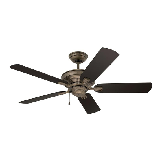
SEA BREEZE
52" Wet Location
Model Numbers
Oil Rubbed Bronze
Appliance White
18.7
Net Weight:
1-800-777-4440
Lbs.
Form No. BP7336-2
U.L. Model No.: CF654
Advertisement
Table of Contents

Related Manuals for Luminance Brands kathy ireland HOME Wet Location SEA BREEZE


Summary of Contents for Luminance Brands kathy ireland HOME Wet Location SEA BREEZE
- Page 1 READ AND SAVE THESE INSTRUCTIONS SEA BREEZE 52” Wet Location Ceiling Fan Owner’s Manual Model Numbers CF654ORB01 - Oil Rubbed Bronze CF654WW01 - Appliance White 18.7 Net Weight: Lbs. Questions, problems, missing parts: Before returning to the store, Call Customer Service 1-800-777-4440 Part No.
-
Page 2: Table Of Contents
Electrical installation should be made or by Luminance Brands could result in personal injury approved by a licensed electrician. or property damage. 3. The outlet box and joist must be securely mounted To reduce the risk of personal injury, do not bend and capable of reliably supporting at least 50 pounds. -
Page 3: Unpacking Instructions
Luminance Brands. Substitution of parts or accessories not designated for use with this product by Luminance Brands could result in personal injury or property damage. Open carton containing fan . Remove top half of styrofoam unit . -
Page 4: Electrical Requirements
1. Unpacking Instructions (Continued) This Manual Is Designed to Make it as Easy as Possible for You to Assemble, Install, Operate and Maintain Your Ceiling Fan THIS FAN IS SUITABLE FOR WET LOCATIONS SUCH AS PORCHES, PATIOS AND DECKS. Tools Needed for Assembly WARNING One Phillips Head Screwdriver One Stepladder... -
Page 5: Ceiling Fan Assembly
3. Ceiling Fan Assembly GREEN GROUND WIRE Remove the Hanger Ball by loosening the Phillips Head Set Screw in the Hanger Ball until the Ball falls freely down the Downrod (Figure 1) . Remove the Pin from the 3 .5” Downrod, then remove 3.5"... - Page 6 3. Ceiling Fan Assembly (Continued) Loosen the Two Upper Phillips Head Set Screws 3.5" DOWNROD in the Motor Coupler for installation of the Downrod (Figure 3) . LOOSEN PHILLIPS HEAD Seat the Downrod in the Motor Coupler (Figure 3) . UPPER SET SCREWS (2) Rotate and align the Downrod Holes with the Two...
- Page 7 3. Ceiling Fan Assembly (Continued) Place the Ceiling Cover over the Downrod (Figure 6) . Be sure that the Ceiling Cover is oriented correctly (Figure 6) . Figure 6 Route the Three Motor Wires through the Hanger Ball (Figure 7) . Reinstall the Hanger Ball on the Downrod as follows: Position the Pin through the Two holes in the Downrod and align the Hanger Ball so the Pin is captured in the...
- Page 8 3. Ceiling Fan Assembly (Continued) M5 x 6 mm WASHER HEAD Turn fan assembly upside down in preparation for BLADE SCREW (3) mounting fan blade assemblies . IMPORTANT: THE SIDE OF THE FAN BLADE HAVING THE RIB LINE MUST BE FACING FAN BLADE UPWARDS AS SHOWN IN FIGURE 9.
-
Page 9: How To Hang Your Ceiling Fan
CAUTION CEILING To reduce the risk of injury, install the fan so that the blades are at least 7 ft. (2.1m) above the floor (Figure 11). WARNING Turning off wall switch is not sufficient. To avoid possible electrical shock, be sure electricity is turned off at the main fuse box or circuit breaker panel before AT LEAST wiring. - Page 10 Securely attach the Hanger Bracket to the Outlet Box using the Two Screws supplied with the Outlet Box . (Figure 13) . OUTLET TWO SCREWS SUPPLIED WITH OUTLET BOX HANGER BRACKET ANTI-ROTATION TAB Figure 13 NOTE: CEILING COVER, SUPPL Y WIRES AND FAN WIRES Carefully lift the Fan and seat the Hanger Ball/ OMITTED FOR CLARITY.
-
Page 11: How To Wire Your Ceiling Fan
WARNING shock. This product is designed to use only those parts NOTE: If you are using an Luminance Brands Light supplied with this product and/or any accessories Fixture with your fan, see Light Fixture Owner’s designated specifically for use with this product Manual for wiring. - Page 12 5. How to Wire Your Ceiling Fan (Continued) Securely connect the Fan Motor Black Wire and Blue Wires to the Supply Black (hot) Wire using Wire FAN MOTOR Connector (supplied) (Figure 17) . BLACK WIRE SUPPLY BLACK (HOT) LISTED WIRE CONNECTOR FAN MOTOR BLUE WIRE...
-
Page 13: Final Assembly
6. Final Assembly Screw the Two Threaded Studs (supplied) into the Tapped Holes in the Hanger Bracket (Figure 19) . THREADED STUDS (2) Figure 19 Lift the Ceiling Cover up to the Threaded Studs and turn until Studs protrude through the Holes in the Ceiling Cover (Figure 20) . -
Page 14: Using Your Ceiling Fan
7. Using Your Ceiling Fan Restore Electrical Power to the Outlet Box by turning the Electricity on at the Main Fuse Box or Circuit Breaker Panel . Check the operation of the Fan by gently pulling on the Pull Chain Switch . REVERSE During Summer Months: Run the Fan Counter- SWITCH... -
Page 15: Energy Efficient Use Of Ceiling Fan
8 - 9 feet above the floor for optimal air near the ceiling down into the occupied space . airflow . Consult your Luminance Brands Retailer for Remember to adjust your thermostat when using your optional mounting accessories . -
Page 16: Repair Parts
11. Repair Parts PARTS BAG U.L. Model No.: CF654... - Page 17 11. Repair Parts Listing Part Numbers Model No. Model No. Description CF654ORB01 CF654WW01 Hanger Ball Assembly, Consisting of: 761655-32 761655 Hanger Bracket (1) — — Hanger Ball (1) — — Downrod (1) — — Parts Bag Containing: 763118 763118-1 Wire Connector, 12 ga. (3) —...
-
Page 18: Troubleshooting
12. Troubleshooting WARNING FOR YOUR OWN SAFETY TURN OFF POWER AT MAIN FUSE BOX OR CIRCUIT BREAKER PANEL BEFORE TROUBLESHOOTING YOUR FAN. TROUBLE PROBABLE CAUSE SUGGESTED REMEDY 1. Fan will not start. 1 . Fuse or circuit breaker blown . 1 . -
Page 19: Ceiling Fan Limited Warranty
What We Will Do To Correct Problems: If the defect is covered by this limited warranty, Luminance Brands will repair or replace the applicable Luminance Brands Ceiling Fan Product at no charge to You. If repair of the Luminance Brands Ceiling Fan Product is not practical or possible within a reasonable time and no replacement Luminance Brands Ceiling Fan Product can be provided, Luminance Brands will refund You the actual purchase price of Your Luminance Brands Ceiling Fan Product. - Page 20 SERIAL NUMBER: DATE CODE: The serial number of this fan can be found on the nameplate on top of the fan housing . The date code can be found on the carton and on top of the fan housing, stamped in ink on a white label . You should record this data above and keep it in a safe place for future use .
Need help?
Do you have a question about the kathy ireland HOME Wet Location SEA BREEZE and is the answer not in the manual?
Questions and answers