Table of Contents
Advertisement
Quick Links
+05C002870 - rel. 1.3 - 17.11.2005
MCH200*03
- µC
: 用于
2
2/4压缩机冷水机组(一个或两个回路) 的控制器
配置图示例 / Configuration example
EV driver
ESP
EV driver
Expansion
EV Driver
EV Driver
board
tLAN
Tx/Rx GND
G0 B1 B2 B3 ID5 ID3 ID1
G GND GND Y GND ID4 ID2
N
L
Line
配置图示例 / Configuration example
EV Driver
Expansion
EV Driver
board
EV driver
ESP
EV driver
tLAN
No1 C1/2 C1/2 C3/4 x
No2 No3 No4 C3/4 x
Tx/Rx GND
DIN
Programming key
Bottom
GND T+
G0 B1 B2 B3 ID5 ID3 ID1
G GND GND Y GND ID4 ID2
To serial link
N
L
Line
/ Electronic controller for chillers with 2/4 compressors (one and two circuits)
RC
阅读并保存
感谢您选择卡乐产品,我们相信您会对卡乐产品感到满意!
这份指导说明书
前言
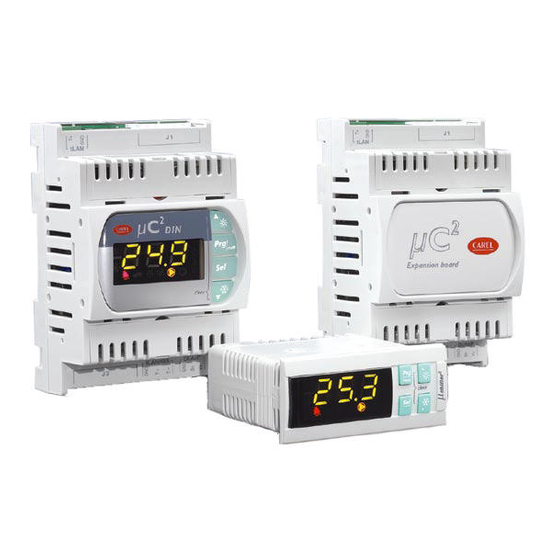
μC
2
是可编程电子控制器,它用于全面管理那些一个回路(两个涡旋压缩机)的冷水机组、热泵、冷凝机组和
风/风机组。其扩展卡 (代码. MCH200002*) 允许最多管理两个回路和四个涡旋压缩机。
连接器的特点
阴性接头(MCH2CON0**)及线缆可以从
CAREL 单独购买或者从厂商Molex购买:
接头 Molex代码
39-01-2120
39-01-2140
最大通/断数: 25个循环。
装配说明
NTC/公制比例传感器的最大长度:
开关量输入连接线缆的最大长度:
电源输出连接线缆的最大长度:
风扇控制输出连接线缆的最大长度:
电源线的最大长度:
tLAN连接线的最大长度:
某些输入输出的使用是由参数的配置来确定的。
N
Line
L
配置图示例
连接端子排
连接端口
14 针
G-G0
B1-GND
No1 C1/2 C1/2 C3/4 x
C5
N02 No3 No4 C3/4 x No5
B2-GND
B3-GND
ID1-GND
ID2-GND
ID3-GND
GND B4 V+
ID4-GND
Key/SPV
ID5-GND
Y-GND
12 针
No1- C1/2
pressure
No2- C1/2
probe
P
No3- C3/4
No4- C3/4
temperature
probe
No5- C5
To program key
TxRx - GND
可拆卸2针端
RS485
digital
子(tLAN)
option
imput
B4-GND(V+公制
可拆卸3针端
子(B4/DB4)
有源压力传感器
Fig. 1
的电源端)
To serial link
参数化编程钥匙选件
面板安装型:在断开控制器电源的情况下,把PSOPZKEY00插入 KEY/SPV 接口。使用可拆卸12针接头(继
电器)连接或断开串行选件和编程钥匙。
DIN导轨安装型:在断开控制器电源的情况下,移开底部的封盖把PSOPZKEY00插入专门的接口
N
Line
注意:配置跳线必须插在A位置(参看技术(MCH200485*)
L
监控选件
面板安装型: 连接串行选件(MCH200485*)至接口KEY/SPV
C5
DIN导轨安装型:移开底部的封盖,在专门的接口插入监视卡FCSER00000
No5
将485屏蔽电缆(2芯屏蔽)与GND,T+,T-端口连接
Top
警告:
•如果使用寿命单个变压器给μC²SE和其附件供电,为了避免损坏设备,把不同控制器或主控制板上的所有
Serial board
G0端口连接到变压器的次线圈的同一端口上;所有G端口连接到变压器次圈的另一个端口上。
•对于居住环境中使用,需要使用屏蔽电缆用于tLAN连接(N55014-1)。
•避免V+和GND间短路,不要损坏设备。
•把电力电缆与传感器,开关量输入和串行电缆分开。
T-
GND B4 V+
•使用单独的变压器给电子控制器供电。
pressure
抗电击保护和维护注意
probe
P
在装配,维护和更换设备前需要断开电源。
temperature
系统由控制板(MCH200*03*)和其它的选件卡(MCH200002*,MCH200485*,MCHRTF****,CONVO-
probe
NOFF*,CONV0/10a*,EVD000040*),这些设备是整合到I类或I I类设备内。抗电击等级由制造商根据系统
digital
的控制设备整合。为了避免因错误的接线引起短路;制造商必须确保设备内控制内置含有该方面的保护。
input
Fig. 2
插针数量为 12 和 14的连接器的 触点代码和允许的线缆横截
面积 (压 线操作请使用代码为 69008-0724的专用Molex工
具):
Molex触点代码
插针数量
允许的线缆横截面积
12
39-00-0077
AWG16 (1.25 mm
2
14
39-00-0038
AWG18-24 (0.90-0.35 mm
39-00-0046
AWG22-28 (0.22-0.06 mm
卡乐可提供预先压好的线材组件,代码是MCHSMLC***.
10 m
10 m
5 m
5 m
3 m
10 m
描述
μC
2
电源
环境温度传感器(风-风机组),水冷蒸发器进口温度传感器(水冷机
组),送风温度传感器
蒸发器出水温度传感器,防冻加热器控制
水冷压力传感器,辅助电加热
通过参数P8设置输入功能(参看用户手册)
通过参数P9设置输入功能(参看用户手册)
高压开关
低压开关
来自外部触点的开机/待机信号,或作为冷凝机组逆向循环运行信号
PWM信号输出,用作冷凝风机控制
压缩机1
辅助电加热/四通阀1(参数H11)
蒸发器水泵/(风机)(风-风机组)(参数H11)
压缩机2/压缩机1能量控制/四通阀1(参数H11)
报警
配有一个扩展板可以连接到μC2上用于控制第二回路(代码MCH00002*)
和电子膨胀阀驱动模块EVD000040*
开关量输入IDB4(参数P13)/公制冷凝压力传感器/室外温度传感器。通
过参数"/4"进行配置
Thank you for your choice. We trust you will be satisfied with your purchase.
Introduction
The μC
2
is an electronic controller for the complete management of chillers, heat pumps, condensing units and air/
air units with one circuit and 2 hermetic compressors. The expansion board (code MCH200002*) allows the mana-
gement of up to 2 circuits and 4 hermetic compressors.
Characteristics of the connectors
The connectors can be purchased separa-
Contact code and cross-section of the connection cables
tely from CAREL (MCH2CON0**) or from
to the 12- and 14-pin connectors (for crimping, use the
the manufacturer, Molex:
special Molex tool‚ 69008-0724):
Molex connector code
number of pins
Molex contact code
39-01-2120
12
39-00-0077
)
39-01-2140
14
39-00-0038
2
)
39-00-0046
2
)
Maximum number of connections/disconnections: 25 cycles. The pre-wired kits MCHSMLC*** are also avai-
lable.
Assembly instructions
Maximum connection cable length, NTC/Ratiometric probes:
Maximum connection cable length, digital inputs:
Maximum connection cable length, power outputs:
Maximum connection cable length, fan control output:
Maximum length, power cables:
Maximum length of tLAN connection cables:
The use of some inputs/outputs depends on the configuration of the parameters.
Configuration example
Connector
Connection
Meaning
14 pin
G-G0
μC2 power supply
B1-GND
Ambient air probe (air-air units), evaporator water inlet probe (water chillers),
outlet air probe
B2-GND
Evaporator water outlet probe, anti-freeze heater control
B3-GND
Condensing pressure control probe, auxiliary heater
ID1-GND
Multifunction input configured by parameter P8 (see user manual)
ID2-GND
Multifunction input configured by parameter P9 (see user manual)
ID3-GND
High pressure switch
ID4-GND
Low pressure switch
ID5-GND
ON/STANDBY from external contact, reverse cycle in operation as conden-
sing unit
Y-GND
PWM output for condenser fan module operation
12 pin
No1- C1/2
Compressor 1
No2- C1/2
Auxiliary heater/ reversing valve 1 (parameter H11)
No3- C3/4
Evaporator pump /(fan) (air/air units) (parameter H11)
No4- C3/4
Compressor 2 / capacity-control comp. 1 / reversing valve 1 (parameter H11)
No5- C5
Alarm
removable 2
TxRx - GND
It allows connecting μC2 with the expansion board for the management of the
pin (tLAN)
second
circuit (code MCH00002*) and valve driver module
EVD000040*
removable 3
B4 - GND (V+
Digital input IDB4 (parameter P13)/ Ratiometric condensing pressure probe /
pin (B4/IDB4)
power supply ra-
Outside temperature probe
tiometric probe)
Can be configured by parameter "/4"
Parameter programming key option
With the controller OFF, insert the key PSOPZKEY00 in the connector KEY/SPV. Connect and disconnect the serial
and programming key options with the 12-pin connector (relay) removed.
Note: the configuration jumper must be inserted in position A (technical leaflet MCH200485*)
Supervisor option
Connect the serial option (code MCH200485*) to the connector KEY/SPV.
Warnings
• If using a single power transformer for the μC
SE and the accessories, connect all the G0 terminals on the various
2
controllers or boards to the same terminal on the secondary, and all the G terminals to the other terminal on the se-
condary, to avoid damaging the instrument;
• For use in residential environments, a shielded cable (conductor + shield) is required for the tLAN connections (EN
55014-1);
• Avoid short-circuits between V+ and GND so as to not damage the instrument:
• Separate the power cables (relay outputs) from the probe, digital input and serial cables;
• Use the power transformer exclusively dedicated to the electronic controllers.
Protection against electric shock and warnings for maintenance
Disconnect the power supply before working on the board during the assembly, maintenance and replacement ope-
rations.
The system made up of the control board (MCH200*03*) and the other optional cards (MCH200002*, MCH200485*,
MCHRTF****, CONVONOFF*, CONV0/10A*, EVD000040*) represents a control device to be incorporated in class I
or class II equipment. The class of protection against electric shock depends on how
ted into the unit made by the manufacturer.
The protection against short-circuits, due to defective wiring, must be guaranteed by the manufacturer of the equip-
ment that the control device is built into.
Cross-section of the cables
allowed
AWG16 (1.25 mm
)
2
AWG18-24 (0.90-0.35 mm
)
2
AWG22-28 (0.22-0.06 mm
2
)
10 m
10 m
5 m
5 m
3 m
10 m
the control device is integra-
Advertisement
Table of Contents

Subscribe to Our Youtube Channel
Related Manuals for Carel MCH200-03 Series


Summary of Contents for Carel MCH200-03 Series
- Page 1 Characteristics of the connectors 连接器的特点 The connectors can be purchased separa- Contact code and cross-section of the connection cables tely from CAREL (MCH2CON0**) or from to the 12- and 14-pin connectors (for crimping, use the 插针数量为 12 和 14的连接器的 触点代码和允许的线缆横截 阴性接头(MCH2CON0**)及线缆可以从...
- Page 2 力传感器 The response time depends on the component used, typical value 90 s 风机输出 卡乐MCHRTF****,CONVONOFF*和CONV0/10A*R的控制信号 B4: NTC temp. probes (10 kW at 25 °C) or CAREL 0 to 5 V or free contact ratiome- tric pressure probes 脉冲信号调节(设置振幅)或值日循环调节,参看用户手册的配置参数部分 无负载电压:5V±10% Fan output Control signal for CAREL MCHRTF****, CONVONOFF* and CONV0/10A* modules Modulation of impulse position (set amplitude) or modulation of the duty-cycle.
Need help?
Do you have a question about the MCH200-03 Series and is the answer not in the manual?
Questions and answers