Table of Contents
Advertisement
ASG-SD2500 & ASG-CT2500
ASG-SD2500 Series Screwdriver & Controller
ASG, Division of Jergens, Inc.
ASG, Division of Jergens, Inc.
15700
15700
S. Waterloo Road | Cleveland, OH
S. Waterloo Road | Cleveland, OH
Phone: (
Phone: (
| Fax: (
| Fax: (
888) 486-6163
888) 486-6163
216) 481-4519
216) 481-4519
Email: asginfo@asg-jergens.com | Web: www.asg-jergens.com
Email: asginfo@asg-jergens.com | Web: www.asg-jergens.com
User's Guide
Version 3.0.3
Version 3.0.4
May 2016
September 2017
44110-3898
44110-3898
Document CT-2500-1 EN
Original Instructions
Advertisement
Table of Contents

Subscribe to Our Youtube Channel
Related Manuals for ASG X-PAQ ASG-SD2500 Series


Summary of Contents for ASG X-PAQ ASG-SD2500 Series
- Page 1 ASG-SD2500 & ASG-CT2500 ASG-SD2500 Series Screwdriver & Controller User’s Guide Version 3.0.3 Version 3.0.4 May 2016 September 2017 Document CT-2500-1 EN ASG, Division of Jergens, Inc. ASG, Division of Jergens, Inc. Original Instructions 15700 15700 S. Waterloo Road | Cleveland, OH S.
- Page 2 ASG Precision Fastening ASG-CT2500 User’s Guide Version 3.0.4 Major Revision: January, 2016 Minor Revision: September, 2017 To download the latest version of this manual visit: www.asg-jergens.com ASG Precision Fastening (888) 486-6163 15700 S. Waterloo Rd. Cleveland, OH 44110 © 2017 Jergens Inc.
-
Page 3: Table Of Contents
Information on Noise Emission Information on Transmitted Vibration Safety Precautions Introduction Installation Controller & Power Requirements Tool Pistol Grip Assembly ASG-SD2500 Functions ASG-SD2500 Operations Run Tool Screen Tool Information Screen Setup Screen Tool Triggering Bolt Counts Bolt Retries Reverse Settings... - Page 4 Input Programming Task Select Enable Bolts Remote Start Reverse Select Remote Reset Remote Halt Output Programming Input/Output Port Pin Guide Graph Screens Graph Data Export Data Screen Erasing Data Downloading Data System Setup Screen Passwords Date/Time Settings Tool Trigger Sensitivity Tool Calibration Controller Information Firmware Updates...
-
Page 5: Declaration Of Conformity
15700 S. Waterloo Rd. Cleveland, Ohio, USA in accordance with the following Directive(s): 2006/42/EC The Machinery Directive 2014/30/EU The Electromagnetic Compatibility Directive hereby declare that: ASG SD2500 Electric Screwdriver System – Tool, Controller, Equipment and Cable ASG-CT2500, ASG-CB2500-[xx][yy], ASG-SD2500-10[zz], Model number... -
Page 6: Information On Noise Emission
Machinery Technical File Reference: ASG-TF-SD2500-01 EMC Technical File Reference: ASG-TF-SD2500-EMC-01 Information on Noise Emission The ASG Division of Jergens Inc., Model SD2500 Electric Screwdriver Sound Pressure and Sound Power Levels per EN ISO 11202 are as follows: Model No: ASG-SD2500... -
Page 7: Safety Precautions
The ASG Division of Jergens Inc., Model SD2500 Electric Screwdriver transmitted vibration levels as found according to EN ISO 60745 are as follows: Screwdriver vibration: < 2.5 m/s Safety Precautions Be sure to read all instructions and precautions contained in this manual, failure to do so may result in personal injury and/or damage to tooling and components. - Page 8 CAUTION - Replace fuse with same type and rating: 250V, 8A, Time-Lag T, 5x20mm 1kA POWER CORD PROTECTION – The power supply cord for this product acts as the main-disconnect. It should be routed or installed in such a matter to protect it from being walked on or pinched. The unit should be powered down completely before connecting or disconnecting the power cable.
- Page 9 Always use safety glasses when using electrical assembly tools. Do not wear loose clothing, dangling jewelry, or loose unbraided long hair when operating this tool. A risk of entanglement is possible that may result in minor injury to the Operator. Keep work area clear of clutter and distractions that may cause the operator to lose control of the tool or the components.
-
Page 10: Introduction
Introduction Thank you for investing in the ASG-SD2500 Precision Screwdriver System from ASG Precision Fastening! This user’s guide will assist you with setting up your system. Please start by finding the serial number labels on each component of your system. - Page 11 Tool Model Number Key ASG-SD2500-20PL Maximum Torque FX – Fixture Mount PL – Push/Lever Start Combo (inlb) PS – Push-to-Start RP – Right Angle (1/4” square) RQ – Right Angle (1/4” hex) Cable Model Number Key ASG-CB2500-10HW Cable Length HW – Heavy Weight Strain Relief (feet) RA –...
-
Page 12: Installation
Controller Installation & Power Requirements: The ASG-CT2500 comes standard with a mounting plate for attaching to the wall, workbench, or tool stand. Secure the controller using the (4) provided holes in the mounting plate. These provided holes are meant for #6 screws. -
Page 13: Tool
Obtain the ASG-SD2500 tool and identify the key slot on the screwdriver connector into which the screwdriver cable connects. Find the red dot on the small end of the cable, and align it to the slot in the screwdriver connector. Insert the cable to the tool firmly until it clicks into place. -
Page 14: Pistol Grip Assembly
Pistol Grip Assembly Should the application require it, ASG Precision Fastening offers an optional Pistol Grip Assembly (P/N ASG-AC2500-PG) for sale. To Install: • Ensure the screwdriver cable is removed from the tool • Use a 5/32” punch to drive out the throttle lever pin that attaches the throttle lever to the screwdriver •... -
Page 15: Asg-Sd2500 Functions
ASG-SD2500 Functions All ASG-SD2500 Screwdrivers are of light-weight aluminum construction and come standard in the inline configuration, with optional pistol grip and lever triggers. Standard Features: • Forward/Reverse Button • LED Status Ring – indicates torque/angle high, low, or pass •... -
Page 16: Asg-Sd2500 Operations
ASG-SD2500 Operation First-time users should take some time to become familiar with the ASG-SD2500 prior to use. With the power to the controller off, cycle the lever and push-to-start spindle to become accustomed to the feel and resistance. Repeat this step with the controller power on, to feel the operation of the tool. -
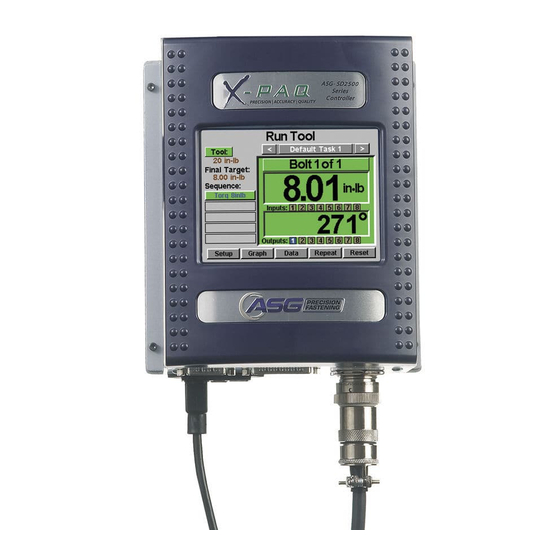
Page 17: Run Tool Screen
Run Tool Screen 1. Task Selection: Shows the user the current task, and allows the user to select one of 32 available tasks. Selecting the button with the task name will bring up the Task Menu where another task may be selected or altered. The arrow keys will advance to the previous or next task. Settings for bolt counts, parameters, inputs, outputs, etc will switch with these actions to the settings of the selected task. - Page 18 10. Data Button: Displays a table that contains rundown characteristics for the last 100 fastening cycles. Additional data is available in the internal memory and can also be downloaded to a USB flash drive from this screen. 11. Repeat Button: Depressing this button keeps the controller on the current bolt in a batch.
-
Page 19: Tool Information Screen
Tool Information Screen This screen displays characteristics of the tool that is currently attached to the ASG-CT2500 controller such as: • • Model Number Maximum Speed • • Serial Number Gear Ratio • • Number of Cycles on the Tool Calibration Value •... -
Page 20: Setup Screen
Setup Screen Entering the setup screen allows you to modify the settings of each task’s parameters, bolt counts, bolt sequences, inputs, outputs, reverse settings, and triggering. Tool Triggering: On the ‘Setup’ screen, each task can be set up to trigger the tool in the way that best fits that task. The tool can be set up for remote start, lever start (if tool is equipped with a lever or pistol-grip attachment), push to start, lever or push to start (together), or lever and push to start. -
Page 21: Bolt Retries
Bolt Retries: To enable this feature, tap the radio button on the task setup screen under the number of bolts. Set the number of retries before lockout by tapping the number and inputting the desired value. A retry is counted when the tool is put into reverse and triggered (run). -
Page 22: Parameter Setup
Parameter Setup: From the task setup screen, select the Parameters button. Shown will be a button for each of the 8 available parameters for that task. Some useful definitions for the Parameter Setup: Target Torque: The torque value at which the tool should stop the fastener rundown (Torque Control parameters only) Target Angle: The angle value at which the tool should stop the fastener rundown (Angle Control parameters... - Page 23 Threshold Torque: The torque reading at which the tool enters the fastening cycle. Once the tool reaches the threshold torque, it will begin to count the angle of revolution until either the final torque or final angle (depending on Torque or Angle Parameter). Run Down Speed: The speed (rpm) that the tool will run (RH or LH rotation) from the time the tool is triggered until either the final target is met, or the downshift point is met (if enabled).
-
Page 24: Bolt Sequences
Bolt Sequences The ‘Bolt Sequences’ button allows the user to select which parameter(s) will run for a given bolt inside each task. To assign a parameter to a bolt, select the bolt number (or multiple bolts if they will all have the same parameter(s)) then tap the button to the right to access the parameter list. -
Page 25: Prevailing Torque
Prevailing Torque Certain applications (such as self-tapping fasteners or fasteners into locking helical inserts) require compensation for the prevailing torque of a fastener in the final torque of the rundown. This can be accomplished using the ‘Calc Prevail Torque’ feature in an angle control parameter. For easy identification, angle control parameters using the prevailing torque option have a purple outline on the parameter blocks. -
Page 26: Prevailing Torque Link
Prevailing Torque Link (GUI v2.6.0 and later) Certain specialized applications may require the calculation of prevailing torque, while also having the ability to recall and compensate for that prevailing torque later in the batch. Example: 2 bolts to be secured with prevailing torque compensation to a snug torque of 3 inlb, then each bolt is re-torqued to 8 inlb with prevailing torque compensation (from the original snug torque operation). - Page 27 Set up (2) nearly identical Torque Control parameters for the final torque of 8 inlb except that the Prevail Torque Link will be different. The parameter assigned to bolt #3 will have the Prevail Torque Link set to 1. The parameter assigned to bolt #4 will have the Prevail Torque Link set to 2.
-
Page 28: Task Setup
Task Setup From either the ‘Run Tool’ or ‘Setup’ screens, tapping the task name will bring up the ‘Task Setup’ screen shown below: All 32 tasks are displayed here and tapping any one will switch to that task. Renaming and Importing Tasks From the ‘Task Setup’... -
Page 29: Exporting Tasks
Exporting Task Settings to USB The ASG-CT2500 controller is capable of exporting the task settings to USB for backup and transfer to other ASG-CT2500 controllers. To accomplish this, insert a USB flash drive with available memory to the port on the controller. -
Page 30: Input Programming
Input Programming There are (8) inputs, as well as a 24V DC and 0V DC supply available through the input connector on the bottom of the controller. On the ‘Run Tool’ screen, there is a row of lights at the bottom showing each of the 8 inputs. When an input is active, the light will illuminate blue to aid in trouble-shooting and setup. -
Page 31: Enable Bolts
• ENABLE BOLTS: From the ‘Run Tool’ Screen: o Tap the ‘Setup’ Button o Make sure the task shown at the top is the one to be programmed. o Tap the ‘Inputs’ Button Assuming that there is only 1 bolt in your sequence, tap the button on the left that says ‘Bolt 1’. You should now see a column of buttons appear in the chart next to each input number. -
Page 32: Remote Start
• REMOTE START: From the ‘Run Tool’ Screen: o Tap the ‘Setup’ Button o Make sure the task shown at the top is the one to be programmed. o Select the ‘Remote Start’ radio button in the ‘Triggering’ section. o Tap the ‘Inputs’ Button o Tap the arrow button on the bottom next to ‘Setup Bolt(s)’... -
Page 33: Reverse Select
• REVERSE ROTATION SELECT: From the ‘Run Tool’ Screen: o Tap the ‘Setup’ Button o Make sure the task shown at the top is the one to be programmed. o Tap the ‘Inputs’ Button o Tap the arrow button on the bottom next to ‘Setup Bolt(s)’ so that ‘Setup Misc’ appears. Select the ‘Reverse’... -
Page 34: Remote Reset
• REMOTE RESET: From the ‘Run Tool’ Screen: o Tap the ‘Setup’ Button o Make sure the task shown at the top is the one to be programmed. o Tap the ‘Inputs’ Button o Tap the arrow button on the bottom next to ‘Setup Bolt(s)’ so that ‘Setup Misc’ appears. Select the ‘Remote Reset’... -
Page 35: Remote Halt
• REMOTE HALT: From the ‘Run Tool’ Screen: o Tap the ‘Setup’ Button o Make sure the task shown at the top is the one to be programmed. o Tap the ‘Inputs’ Button o Tap the arrow button on the bottom next to ‘Setup Bolt(s)’ so that ‘Setup Misc’ appears. Select the ‘Remote Halt’... -
Page 36: Output Programming
Output Programming There are (8) programmable outputs, 24V DC, and 0V DC supply available through the output connector on the bottom of the controller. See the chart at the end of this section for pin location and other technical information. All the outputs can be set up with the following instructions from the ‘Run Tool’... - Page 37 AVAILABLE OUTPUT CRITERIA: • BOLT - SUCCESS: All torque and angle requirements fall within the predefined acceptable HL and LL ranges of the programmed parameter • BOLT – FAIL LOW: Any torque and/or angle requirement fell below the predefined acceptable LL ranges of the programmed parameter •...
-
Page 38: Input/Output Port Pin Guide
Input/Output Port Pin Guide Input Port (DB15 Male) Function 0 VDC (from internal power supply) Input 1 Common Inputs 3 & 4 Input 4 Input 5 Input 7 * Input 8 * 24 VDC (from internal power supply) Common Inputs 1 & 2 Input 2 Input 3 Common Inputs 5 &... - Page 39 Output Port (DB25 Male) Function 0 VDC (from internal power supply) 0 VDC (from internal power supply) Output 1 – Normally Closed Output 2 – Normally Closed Common – Outputs 3 & 4 Output 3 – Normally Open Output 4 – Normally Open Output 5 –...
-
Page 40: Graph Screens
Graph Screens In order to assist the user with setting up and trouble-shooting problem joints, the latest rundown is stored in the controller in graph form. From the ‘Run Tool’ screen, tap the ‘Graph’ button at the bottom of the screen. Along the bottom of the screen can be found the available graphs, tap the appropriate button to view: •... - Page 41 • Speed vs. Time: Graphs the last rundown with Speed on the Y axis in rotations per minute (rpm), and Time on the X axis in milliseconds (ms). • Power vs. Time: Graphs the last rundown with Power on the Y axis in Watts (W), and Time on the X axis in milliseconds (ms).
-
Page 42: Graph Data Export
In order to enable the graph data export function, a key file must be saved to a USB flash drive and inserted to the controller. This file can be obtained from ASG and saved to the USB main directory inside a folder named ‘Keys’. -
Page 43: Data Screen
Data Screen For data traceability, rundown information is stored in table form for view and download from the controller. To access this data, tap the ‘Data’ button on the bottom of the ‘Run Tool’ screen. The last 100 rundowns since the last controller reboot is available to view on screen. -
Page 44: Downloading Data
Downloading Data To download data to a USB flash drive, insert a flash drive with available memory into the port on the bottom of the controller. Tap the ‘Export Data’ button at the bottom of the data table, and then select either to download just the Data Screen Contents, or choose a date range for which you wish to download the data. -
Page 45: System Setup Screen
System Setup Screen The ‘System Setup’ screen allows the user to set system controls and tool settings. See the following sections for further information. Passwords From the ‘System Setup’ screen, tap the ‘Passwords’ button. The controller allows (3) individual passwords, each password allows access to the controller when locked. - Page 46 Modifying features in a locked controller: Navigate to the setting or feature that needs to be modified and tap the appropriate button or number. The controller will then prompt the user for a password to unlock the controller. Once a password is accepted, settings can be changed on any screen.
-
Page 47: Date/Time Settings
Date/Time Settings To set the controller’s date and time, tap the ‘Date/Time’ button on the ‘System Setup’ screen. Adjust the date and time with the up and down arrow keys above and below each number. Note: the time is formatted in a 24 hour format, and the date is in MM/DD/YY format. -
Page 48: Tool Trigger Sensitivity
The controller allows the user to set the sensitivity of both the Push-to-Start and the Lever Start (when equipped) features of the ASG-SD2500 tool to suit individual user or application preferences. To adjust these settings, tap the ‘Tool Trig Sensitivity’ button on the ‘System’ screen. -
Page 49: Tool Calibration
Tool Calibration To view the calibration value of the tool connected to the controller, tap the ‘Tool Cal’ button on the ‘System’ screen. The calibration value will be displayed, and can be modified if required. CAUTION: Tapping on the Calibration Value will take you to a screen where the value can be manually changed. This screen is for qualified calibration technicians only. -
Page 50: Controller Information
Controller Information To view basic information about the controller and to give the controller a name, tap the ‘Controller Info’ button on the ‘System’ screen. This screen displays the following: • Controller Name • Controller Serial Number • GUI Board Firmware Version •... -
Page 51: Firmware Updates
The USB flash drive must be FAT32 formatted for this feature to work properly. Failure to use a properly formatted flash drive can result in firmware corruption and require the controller to be serviced at ASG to reset it to proper function. -
Page 52: Service & Warranty
Service & Warranty Service Should a product need to be returned for any reason, please contact ASG for a return authorization number prior to shipping an item for repair. Call us at (888) 486-6163 or email us at info@asg-jergens.com •... - Page 53 5. Maximum Torque 6. Maximum Speed 7. Gear Ratio 8. Calibration Value ASG, Division of Jergens, Inc. S. Waterloo Road | Cleveland, OH | Phone: ( | Fax: ( | Email: asginfo@asg-jergens.com | Web: www.asg-jergens.com 15700 44110-3898 888) 486-6163 216) 481-4519...
- Page 54 3. Task Name • Task Name’s 13-24 4. Export Task Files ASG, Division of Jergens, Inc. S. Waterloo Road | Cleveland, OH | Phone: ( | Fax: ( | Email: asginfo@asg-jergens.com | Web: www.asg-jergens.com 15700 44110-3898 888) 486-6163 216) 481-4519...
- Page 55 • Task Name’s 25-32 4. Export Task Files 1. Export Complete ASG, Division of Jergens, Inc. S. Waterloo Road | Cleveland, OH | Phone: ( | Fax: ( | Email: asginfo@asg-jergens.com | Web: www.asg-jergens.com 15700 44110-3898 888) 486-6163 216) 481-4519...
- Page 56 2. Clear 3. Delete 4. Enter 5. Shift 6. Space 7. Cancel ASG, Division of Jergens, Inc. S. Waterloo Road | Cleveland, OH | Phone: ( | Fax: ( | Email: asginfo@asg-jergens.com | Web: www.asg-jergens.com 15700 44110-3898 888) 486-6163 216) 481-4519...
- Page 57 1. Task Name 2. Rename 3. Import ASG, Division of Jergens, Inc. S. Waterloo Road | Cleveland, OH | Phone: ( | Fax: ( | Email: asginfo@asg-jergens.com | Web: www.asg-jergens.com 15700 44110-3898 888) 486-6163 216) 481-4519...
- Page 58 15. Downshift Torque 16. Downshift Speed 17. Tool Maximums 18. Torque 19. Speed ASG, Division of Jergens, Inc. S. Waterloo Road | Cleveland, OH | Phone: ( | Fax: ( | Email: asginfo@asg-jergens.com | Web: www.asg-jergens.com 15700 44110-3898 888) 486-6163 216) 481-4519...
- Page 59 15. Downshift Torque 16. Downshift Speed 17. Tool Maximums 18. Torque 19. Speed ASG, Division of Jergens, Inc. S. Waterloo Road | Cleveland, OH | Phone: ( | Fax: ( | Email: asginfo@asg-jergens.com | Web: www.asg-jergens.com 15700 44110-3898 888) 486-6163 216) 481-4519...
- Page 60 Cancel ASG, Division of Jergens, Inc. S. Waterloo Road | Cleveland, OH | Phone: ( | Fax: ( | Email: asginfo@asg-jergens.com | Web: www.asg-jergens.com 15700 44110-3898 888) 486-6163 216) 481-4519...
- Page 61 16. Bolt Number 17. Timeout 18. Tool Maximums 19. Torque 20. Speed ASG, Division of Jergens, Inc. S. Waterloo Road | Cleveland, OH | Phone: ( | Fax: ( | Email: asginfo@asg-jergens.com | Web: www.asg-jergens.com 15700 44110-3898 888) 486-6163 216) 481-4519...
- Page 62 16. Bolt Number 17. Timeout 18. Tool Maximums 19. Torque 20. Speed ASG, Division of Jergens, Inc. S. Waterloo Road | Cleveland, OH | Phone: ( | Fax: ( | Email: asginfo@asg-jergens.com | Web: www.asg-jergens.com 15700 44110-3898 888) 486-6163 216) 481-4519...
- Page 63 9. Outputs 10. Setup 11. Graph 12. Data 13. Repeat 14. Reset ASG, Division of Jergens, Inc. S. Waterloo Road | Cleveland, OH | Phone: ( | Fax: ( | Email: asginfo@asg-jergens.com | Web: www.asg-jergens.com 15700 44110-3898 888) 486-6163 216) 481-4519...
- Page 64 19. Speed 20. Power 21. System Setup 22. % Tool Capacity ASG, Division of Jergens, Inc. S. Waterloo Road | Cleveland, OH | Phone: ( | Fax: ( | Email: asginfo@asg-jergens.com | Web: www.asg-jergens.com 15700 44110-3898 888) 486-6163 216) 481-4519...
- Page 65 19. Speed 20. Power 21. System Setup 22. % Tool Capacity ASG, Division of Jergens, Inc. S. Waterloo Road | Cleveland, OH | Phone: ( | Fax: ( | Email: asginfo@asg-jergens.com | Web: www.asg-jergens.com 15700 44110-3898 888) 486-6163 216) 481-4519...
- Page 66 19. Speed 20. Power 21. System Setup 22. % Tool Capacity ASG, Division of Jergens, Inc. S. Waterloo Road | Cleveland, OH | Phone: ( | Fax: ( | Email: asginfo@asg-jergens.com | Web: www.asg-jergens.com 15700 44110-3898 888) 486-6163 216) 481-4519...
- Page 67 2. Parameter Name • Parameter Name’s 1-8 3. Torque Control 4. Angle Control ASG, Division of Jergens, Inc. S. Waterloo Road | Cleveland, OH | Phone: ( | Fax: ( | Email: asginfo@asg-jergens.com | Web: www.asg-jergens.com 15700 44110-3898 888) 486-6163 216) 481-4519...
- Page 68 6. Parameter Name 7. Delay 8. Select 9. Clear Bolt(s) Sequence ASG, Division of Jergens, Inc. S. Waterloo Road | Cleveland, OH | Phone: ( | Fax: ( | Email: asginfo@asg-jergens.com | Web: www.asg-jergens.com 15700 44110-3898 888) 486-6163 216) 481-4519...
- Page 69 5. Require 6. Currently 7. Setup Misc 8. Reset Inputs 9. Ignore ASG, Division of Jergens, Inc. S. Waterloo Road | Cleveland, OH | Phone: ( | Fax: ( | Email: asginfo@asg-jergens.com | Web: www.asg-jergens.com 15700 44110-3898 888) 486-6163 216) 481-4519...
- Page 70 9. Setup Misc 10. Reset Inputs 1. Outputs 2. Function 3. None ASG, Division of Jergens, Inc. S. Waterloo Road | Cleveland, OH | Phone: ( | Fax: ( | Email: asginfo@asg-jergens.com | Web: www.asg-jergens.com 15700 44110-3898 888) 486-6163 216) 481-4519...
- Page 71 14. Solid 15. Momentary 16. Active 17. Repeating 18. Active 19. Inactive ASG, Division of Jergens, Inc. S. Waterloo Road | Cleveland, OH | Phone: ( | Fax: ( | Email: asginfo@asg-jergens.com | Web: www.asg-jergens.com 15700 44110-3898 888) 486-6163 216) 481-4519...
- Page 72 5. Tool Calibration 6. Controller Information 7. Touch Screen Calibration 8. LCD Brightness ASG, Division of Jergens, Inc. S. Waterloo Road | Cleveland, OH | Phone: ( | Fax: ( | Email: asginfo@asg-jergens.com | Web: www.asg-jergens.com 15700 44110-3898 888) 486-6163 216) 481-4519...
- Page 73 2. Clear 3. Delete 4. Shift 5. Cancel 6. Space 7. Enter ASG, Division of Jergens, Inc. S. Waterloo Road | Cleveland, OH | Phone: ( | Fax: ( | Email: asginfo@asg-jergens.com | Web: www.asg-jergens.com 15700 44110-3898 888) 486-6163 216) 481-4519...
- Page 74 4. Push to Start Threshold 5. Activate Push to Detect Range ASG, Division of Jergens, Inc. S. Waterloo Road | Cleveland, OH | Phone: ( | Fax: ( | Email: asginfo@asg-jergens.com | Web: www.asg-jergens.com 15700 44110-3898 888) 486-6163 216) 481-4519...
- Page 75 4. GUI Board 5. Firmware Version 6. Firmware Update 7. Controller Board ASG, Division of Jergens, Inc. S. Waterloo Road | Cleveland, OH | Phone: ( | Fax: ( | Email: asginfo@asg-jergens.com | Web: www.asg-jergens.com 15700 44110-3898 888) 486-6163 216) 481-4519...
- Page 76 9. Torque High Level 10. Torque Low Level 11. Downshift 12. Threshold ASG, Division of Jergens, Inc. S. Waterloo Road | Cleveland, OH | Phone: ( | Fax: ( | Email: asginfo@asg-jergens.com | Web: www.asg-jergens.com 15700 44110-3898 888) 486-6163 216) 481-4519...
- Page 77 9. Torque High Level 10. Torque Low Level 11. Downshift 12. Threshold ASG, Division of Jergens, Inc. S. Waterloo Road | Cleveland, OH | Phone: ( | Fax: ( | Email: asginfo@asg-jergens.com | Web: www.asg-jergens.com 15700 44110-3898 888) 486-6163 216) 481-4519...
- Page 78 5. Angle 6. Torque vs. Angle 7. Speed 8. Power vs. Time ASG, Division of Jergens, Inc. S. Waterloo Road | Cleveland, OH | Phone: ( | Fax: ( | Email: asginfo@asg-jergens.com | Web: www.asg-jergens.com 15700 44110-3898 888) 486-6163 216) 481-4519...
- Page 79 8. Good 9. Aborted 10. Export Data 11. Erase 12. Next ASG, Division of Jergens, Inc. S. Waterloo Road | Cleveland, OH | Phone: ( | Fax: ( | Email: asginfo@asg-jergens.com | Web: www.asg-jergens.com 15700 44110-3898 888) 486-6163 216) 481-4519...
- Page 80 2. Data Screen Contents 3. Date Range 4. To 5. Export ASG, Division of Jergens, Inc. S. Waterloo Road | Cleveland, OH | Phone: ( | Fax: ( | Email: asginfo@asg-jergens.com | Web: www.asg-jergens.com 15700 44110-3898 888) 486-6163 216) 481-4519...
- Page 81 2. Data Screen Contents 3. Date Range 4. To 5. Export 6. Complete ASG, Division of Jergens, Inc. S. Waterloo Road | Cleveland, OH | Phone: ( | Fax: ( | Email: asginfo@asg-jergens.com | Web: www.asg-jergens.com 15700 44110-3898 888) 486-6163 216) 481-4519...
Need help?
Do you have a question about the X-PAQ ASG-SD2500 Series and is the answer not in the manual?
Questions and answers