Table of Contents

Subscribe to Our Youtube Channel
Related Manuals for First Choice Lincat Opus 800


Summary of Contents for First Choice Lincat Opus 800
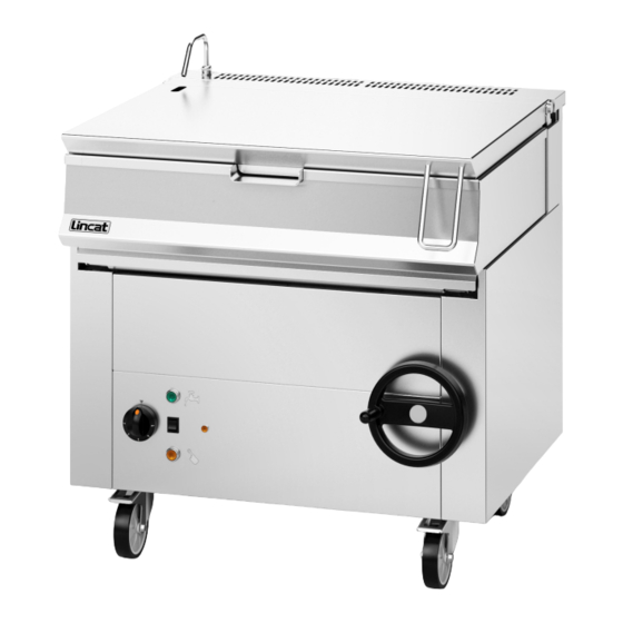
- Page 1 SPARE PARTS DIAGRAM FOR Bratt Pan Opus 800 OG8801N/P First Choice Group Blakeney Way, Kingswood Lakeside Cannock, Staffs, WS11 8LD TEL: 01543 577778 FAX: 01543504141 Email: enquires@firstchoice-cs.co.uk Web: www.firstchoice-cs.co.uk...
- Page 2 Installation, Operating, Servicing and Conversion Instructions Opus 800 Gas Heated Tilting Bratt Pan OG8801 Please make a note of your product details for future use: Date Purchased:_________________________ Model Number:__________________________ Serial Number:__________________________ Dealer:_________________________________ _______________________________________ IS 582 ECN 3851 Page 1 of 17...
-
Page 3: Table Of Contents
CONTENTS Important Information Warnings and Precautions Technical Data Checklist of Enclosures Installation and Commissioning Operating Instructions Cleaning Servicing, Maintenance and Component Replacement Conversion Fault Finding Spare Parts List Accessories Service Information and Guarantee IMPORTANT INFORMATION Read these instructions carefully before using this product, paying particular attention to all sections that carry warning symbols, caution symbols and notices. -
Page 4: Warnings And Precautions
WARNINGS AND PRECAUTIONS This appliance must be installed, commissioned, serviced and converted by a qualified person in accordance with national and local regulations in force in the country of installation. Strip plastic coating and clean the appliance before use. During operation parts may become hot - avoid accidental contact. Parts protected by the manufacturer shall not be adjusted by the user. -
Page 5: Checklist Of Enclosures
CHECK LIST OF ENCLOSURES Warranty card Instructions manual INSTALLATION AND COMMISSIONING Site this appliance beneath an extraction canopy for the removal of combustion products. When making the gas connection, fit an isolating cock into the supply line close to the appliance for emergency shutdown or servicing purposes. - Page 6 Figure 1 This appliance must be earthed. If replacing the plug connect the terminals as follows: Green and Yellow wire Earth Blue wire Neutral N Brown wire Live Means of isolation with at least 3mm contact separation in all poles must be incorporated into the fixed wiring of this appliance.
- Page 7 The appliance is type ‘A’. Rooms must be ventilated in compliance with existing technical regulations. The airflow must not be less than 2 cubic metres per hour per kW of installed capacity. If the appliance must be fitted near walls, partitions kitchen furniture etc we recommend they are made from non-inflammable material, otherwise they should be covered with a suitable heat-resistant material.
- Page 8 Inspection of the electrical supply Start the appliance following the instructions for use. Check the heating devices are working correctly. Raise and lower the tank, dependant on model. Ensure that the cut out operates when the tank is raised, and that power is restored when the tank is lowered into the working position again.
-
Page 9: Operating Instructions
OPERATING INSTRUCTIONS Only qualified or trained personnel should use this appliance. Do not use this appliance as a deep or shallow fryer. Warning: The main burner will only ignite when the tank is positioned correctly on the heating chamber. Warning: When griddling in the tank the addition of water or stock should only take place at a temperature and rate that avoids a severe reaction in the pan which could cause scolds and burns if done carelessly Figure 4... - Page 10 The Safety thermostat can be reset by pressing the button (g) after the appliance has cooled down The gas valve control knob displays the following: Off 1 to 5 where 1 approximates to 100°C and 5 approximates to 280°C Caution: Ensure that the container into which the food product is emptied is suitable to contain food at a high temperature.
-
Page 11: Cleaning
CLEANING Do not use a water jet or steam cleaner, and do not immerse this appliance. Always disconnect the appliance from the mains supply before cleaning or maintenance. Clean all panels with warm water and mild detergent do not use abrasive materials. Dry with a soft cloth. - Page 12 Gently pull out the bracket from appliance enough to be able to unplug the igniter lead ends from the igniters and secure them temporarily whilst replacing the igniters Reconnect igniter leads Replace bracket Check operation is restored Burners, Remove lower and upper control panel facia. Remove burner pipework Unscrew burner Remove...
-
Page 13: Conversion
Figure 3 Micro switch Remove the front lower control panel Disconnect the electrical connections of the device. Replace the component. Tank Remove right hand side panel and remove and replace components as necessary Water solenoid Remove the front lower control panel Remove and replace the component. -
Page 14: Fault Finding
FAULT FINDING Please refer to the Service Help Desk number on the final page of this manual. POTENTIAL TROUBLESHOOTING AND SOLUTIONS Even during correct use of the appliance, malfunctions and breakdowns may occur. Common situations are listed below, and checks an installer should make before contacting the technical support centre are indicated. -
Page 15: Spare Parts List
SPARE PARTS LIST Part Number Description Used on 719-005-00 IGNITION ELECTRODE 776-029-00 MOMENTARY PUSH BUTTON 778-016-00 GAS VALVE CONTROLLER 872-027-00 TRAPEZOIDAL THREADED 872-038-00 SHOULDERED SWIVEL NUT 872-039-00 BRATT LID HANDLE BE40 PILLAR BLOCK BEARING BU253 4KW TUBULAR BURNER BU254 FLANGED JOURNAL BEARING CA143 CASTOR OPUS SWIVEL CA145... - Page 16 770 is with lid up and flue top removed IS 582 ECN 3851 Page 15 of 17...
-
Page 17: Accessories
ACCESSORIES Part Number Description Used on SERVICE INFORMATION For help with the installation, maintenance and use of your Lincat equipment, please contact our service department: 01522 875520 For non-UK customers, please contact your local Lincat dealer All service work, other than routine cleaning should be carried out by one of our authorised service agents. - Page 18 • Damage due to incorrect installation, modification, unauthorised service work or damage due to scale, food debris build-up, etc. The manufacturer disclaims any liability for incidental, or consequential damages. Attendance is based on reasonable access to the appliance to allow the authorised technician to carry out the warranty work.
Need help?
Do you have a question about the Lincat Opus 800 and is the answer not in the manual?
Questions and answers