Table of Contents
Advertisement
Quick Links
OPERATION AND MAINTENANCE MANUAL
1. Introduction
1.1. General
1.2. Technical data
1.3. System description
2. Installation
2.1. General criteria and material required
2.2. Components mounting
2.3. Water intake
2.4. Hydraulic connections
2.5. Electric connections
3. Operating procedures
3.1. By-pass activation
3.2. First start-up procedure
3.3. Normal operating procedure
4. Maintenance
4.1. Shutdown procedure
4.2. Maintenance and recurrent inspections
4.3. Troubleshooting
5. Safety cautions
6. Most frequent operations summary table
7.Warranty
1
Rev. 2012
Advertisement
Table of Contents
Troubleshooting

Subscribe to Our Youtube Channel
Related Manuals for Schenker MODULAR 30 Electron

Summary of Contents for Schenker MODULAR 30 Electron
- Page 1 OPERATION AND MAINTENANCE MANUAL 1. Introduction 1.1. General 1.2. Technical data 1.3. System description 2. Installation 2.1. General criteria and material required 2.2. Components mounting 2.3. Water intake 2.4. Hydraulic connections 2.5. Electric connections 3. Operating procedures 3.1. By-pass activation 3.2.
- Page 2 1. Introduction 1.1 General Thank you for choosing a Schenker Watermaker which we know will give you years of service, making life onboard more enjoyable. To ensure the maximum efficiency of your Schenker Watermaker and its trouble free working, Please read this manual and to keep it onboard for reference.
- Page 3 1. Introduction 1.2 Technical data WATERMAKER GROUP Dimensions Length: 68 cm Width: 20 cm Height: 30 cm Net weight: 24 Kgs. Connections: Seawater intake holder for hose int. diam. 16 mm. Salt water outlet holder for hose int. diam. 16 mm. Fresh water outlet compression fitting for hose int.
- Page 4 This action will not be required in normal circumstances as the unit has been pre calibrated at the factory. Before changing the settings please call a Schenker Service Point. The grey box contains the power relays that activate the pumps electric motors.
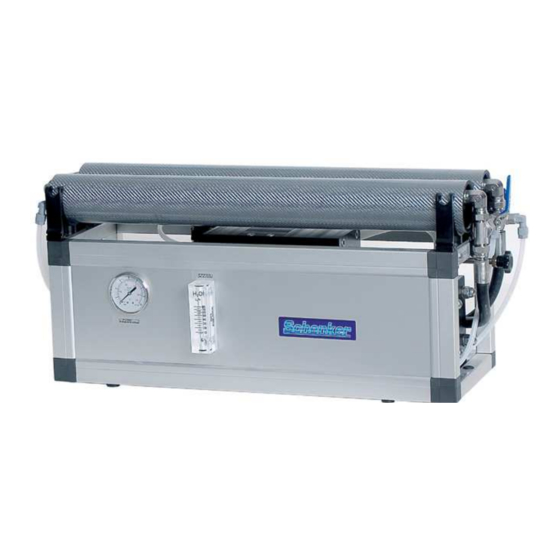
- Page 5 WATERMAKER GROUP. 1. Reverse osmosis membranes 2. Manometer 3. Flow meter 4. Depressurization valve The watermaker group is constituted of the following components: The Reverse osmosis membranes, inside the silver high-pressure vessel are used to separate the intake high-pressure seawater into two flows: one for the salt-water waste and one for fresh water production.
- Page 6 Depressurization valve Reset valve Positioner Computer. It is installed in a box outside the system. On the box is installed a by-pass key that exclude the electronics and allow to run the system manually. Pressure switch (probe). It is a little steel device, mounted on the aluminum structure. It is connected to the computer throw the cables 5 / + .
- Page 7 2. Installation 2.1 General criteria It is important to plan carefully the activity prior to start the installation works, evaluating any possible alternative solution. The fundamental choices to make are: Finding of seawater intakes and any necessary fittings. Positioning of main units . Positioning of pumps operation automatic circuit breakers.
- Page 8 2. Installation 2.3 Water intakes The necessary hydraulic intakes are: • Seawater intake It is ideal a specific sea water intake, size ¾” min. in a central position, well under the water surface even when the vessel is well heeled over. The skin fitting is recommended.
- Page 9 2. Installation 2.4 Hydraulic connections Exhausted discharge Plumb to pressure side of boat fresh water Reinforced hose PN15 min int. dia. 16 mm. “Armovin” type hose int. dia. 16 mm. Pressurized fresh water valve Pump Elecrovalve Non return valve 5 micron filter Net filter Swan neck upward - Disharge Water inlet...
- Page 10 PUMP CONNECTIONS: Connect the in/out hose to the pump as follows: WATERMAKER CONNECTIONS: IN – (sea water inlet from the pump) Make use, for this connection, of the external holder located on the left side of the watermaker (marked IN). OUT (Discharge outboard) Make use, for this connection, of the holder located on top of the pressure amplifier, inside the watermaker unit (marked OUT).
- Page 11 2.Installation 2.5 Electric connections Remote control panel mounting The remote control panel has the following dimensions: width 12 cm height 8 cm. It can be embedded installed on any boat covering panel, on condition that the area behind is free of humidity and condense and there is enough depth to house the rear part of the panel (approx.
- Page 12 The connection general diagram is the following: Clamp connect to cable section negative battery see table positive battery see table pump see table pump see table electrovalve (on the AC filter) 2,5 mm2 electrovalve (on the AC filter) 2,5 mm2 pressure switch (on the watermaker) 2,5 mm2 pressure switch (on the watermaker) 2,5 mm2 Remote control panel-to-computer wiring...
- Page 13 3. Operation PUMP 1 AUT. WASHING prearrangment selectors START STOP MAN. WASHING ALLA illuminated control push-buttons 3.1 By-pass activation The by-pass is activated by turning the key type switch located on the small box connected to the microcomputer clockwise. When the by-pass is activated, all the electronic functions (diagnostic, automatic washing, etc.) are disabled, and the unit works in manual mode (the pumps 1 and 2 are activated acting directly on the PUMP1 and PUMP2 selectors).
- Page 14 3. Operation 3.2. First start-up procedure The first start-up procedure is necessary to start a new plant for the first time or to restart it after having performed the laying up procedure. The purpose of the procedure is essentially purge the air from the system.
- Page 15 Warning: the electronic computer is equipped with a minimum voltage block calibrated at about 10,8 volt (12 VDC systems) and at 21,8 volt (24 VDC systems). This protection is necessary to avoid potential batteries damage (that could prejudice the functioning of others accessories) if the system works for a long with low charged batteries. At start (when you push the START button) the watermaker electric absorption has a little peak.
- Page 16 Fresh water production cycle with automatic washing. For use when the watermaker is not used on a daily basis or when automatic washing is required after every water making session.) 1. Preset the pumps by turning the PUMP1 switch clockwise. 2.
-
Page 17: Reset Procedure
This phenomenon, besides being very rare, does no harm to the system, but it is necessary to reset the valve with the following simple procedure: RESET PROCEDURE 1. Turn the system off. 2. Open the reset valve (lever in horizontal position). 3. - Page 18 This is used for 'pickling' the watermaker when not in use and as part of the general cleaning process. See 4.1 Shutdown procedure Schenker No 2 is an alkaline base organic cleaner. If the watermaker has been left standing without pickling or has a 'bag egg” smell, cleaning with Schenker No2 will remove this.
- Page 19 4. Maintenance 4.2 Verifications and periodic maintenance The following periodic procedures are to be followed to maintain trouble free operation: OPERATION EVERY PROCEDURE Check and clean Strainer check and Every 5 days cleaning Unscrew anticlockwise the filter holder. 5 micron cartridge Every 15-20 days in replacement average conditions (4...
-
Page 20: Troubleshooting
Perform Reset Dirty filter Replace cartridge pressure Dirty membranes Perform cleaning cycle Trouble in the cycling system Contact a Schenker service point While functioning the Pump pressure switch is not Calibrate pressure switch calibrated pump momentarily shuts Dirty filter or membranes... -
Page 21: Electronic Troubleshooting
ELECTRONIC TROUBLESHOOTING When pressing start button the system will not start Check that the by-pass is not switched on (bypass switch turned anticlockwise) and that at least one pump is activated (switch PUMP1 or PUMP2 turned on). If the system still fails to start... Check that electric cables are properly connected, follow the wiring scheme indicated in the manual and that the main automatic circuit breaker is in place. -
Page 22: Safety Warnings
Ensure the watermaker is correctly installed by contacting a Schenker service point. The water produced by a Schenker Modular 60 watermaker using clean sea water will have an average quality of 300ppm TDS. Unless the correct cleaning procedures are carried out in accordance with this manual, there may be bacteria present in the produced water. -
Page 23: Warranty
In case of repairs under guarantee performed by our technicians on the customer vessel, the faulty parts replacement cost will be at Schenker's expense, while manpower and travel expenses will be charged to the customer. The guarantee does not include faults caused by negligence in operating, maintenance and installation of the device (if not carried out by an authorised Schenker Service point).
Need help?
Do you have a question about the MODULAR 30 Electron and is the answer not in the manual?
Questions and answers