Advertisement
Quick Links
IMPORTANT
Carefully remove all the parts from the carton and
place them individually on a soft cloth to prevent
scratches or other damage.
Carefully and strictly follow these assembly instructions
to ensure a completed product as designed.
Do not use power tools above 8 volts to assemble.
Part List
C.
Base
1 pc.
I.
J.
Rail
Base
2 pcs.
1 pc.
K.
Plinth
1 pc.
R.
Support
1 pc.
Q.
S.
Divider
Support
1 pc.
2 pcs.
T.
U.
Door
Door
1 pc.
1 pc.
Carton 20 05010 0941 is also needed for assembly.
Tool(s) required for assembly: Phillips screwdriver, Level
Home Styles Customer Service: www.homestyles-furniture.com,
servicedesk@homestyles-furniture.com,
20 05010 0942
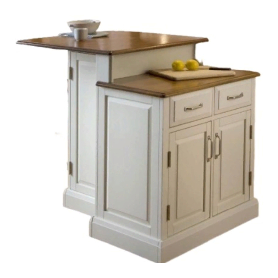
Kitchen Island
D.
E.
Plinth
Plinth
1 pc.
1 pc.
L.
Side Panel
1 pc.
V.
W.
Door
Door
1 pc.
1 pc.
F.
G.
Back Panel
Back Panel
1 pc.
1 pc.
N.
Middle Panel
M.
1 pc.
Side Panel
1 pc.
X.
Shelf
3 pcs.
Y.
Shelf
2 pcs.
888-680-7460, 877-831-0319
H.
Front Panel
1 pc.
O.
Back Stretcher
1 pc.
P.
Front Rail
1 pc.
Z.
Drawer
2 pcs.
Refer to later page(s) of these
instructions for drawer assembly.
Advertisement

Subscribe to Our Youtube Channel
Related Manuals for Home Styles 20 05010 0942


Summary of Contents for Home Styles 20 05010 0942
- Page 1 Refer to later page(s) of these 1 pc. 1 pc. 1 pc. 1 pc. 2 pcs. instructions for drawer assembly. Carton 20 05010 0941 is also needed for assembly. Tool(s) required for assembly: Phillips screwdriver, Level Home Styles Customer Service: www.homestyles-furniture.com, servicedesk@homestyles-furniture.com, 888-680-7460, 877-831-0319...
- Page 2 Assembly Instructions 2/7 IMPORTANT Ÿ Use a soft cloth between these parts and the floor. Ÿ Do not use power tools above 8 volts to assemble. Ÿ Do not tighten all the bolts until each part is properly assembled. Ÿ The unit must be level to work properly.
- Page 3 Assembly Instructions 3/7 STEP 3 Attach Back Panel (F) to Back Panel (G). Attach unit form Step 2 and Rails (I) to unit with Cam Locks. Attach Front Panel (H) to unit with Cam Locks. Cam Lock Screw Cam Lock Screw Cam Lock Screw Cam Lock Screw STEP 4...
- Page 4 Assembly Instructions 4/7 STEP 5 Cam Lock Attach Middle Panel (N) to Base (J) with Head Cap Bolts. (See Figure 4) Attach Plinth (K) to unit with Cam Locks. Figure 4 Head Cap Bolt Wood Screw for Plinth STEP 6 Attach Side Panel (L) to unit with Cam Locks and Wood Screw for Plinth.
- Page 5 Assembly Instructions 5/7 STEP 8 Attach Top (B) to unit with Head Cap Bolts. Head Cap Bolt Cam Lock Screw Figure 5 Cam Lock Head Cap Bolt (short) STEP 9 Attach unit form Step 3 to unit from Step 8 with Cam Locks and Head Cap Bolts (short).
- Page 6 Assembly Instructions 6/7 Drawer (Z) Wood Screw (long) Bottom STEP 10 Attach Drawer Front (Z1) and Drawer Back (Z2) to Drawer Side (Z3) with Wood Screws (long). Attach Drawer Side (Z4) to unit with Wood Screws (long). Roller at back STEP 11 Wood Screw (short) Slide Drawer Bottom (Z5) into the grooves...
- Page 7 Assembly Instructions 7/7 STEP 13 Insert Adjustable Pins into side panels at desired level. Head Cap Bolt Place Shelves (X) into position. Attach Doors (T) and (U) to unit by sliding door hinges into side panel hinges. (See Figure 5) Attach Top (A) to unit with Head Cap Bolts.
- Page 8 Buff with a dry clean cloth. Home Styles will provide replacements free of charge for missing or damaged hardware or parts within 30 days of purchase. Digital images of the defective parts may be required. If the product was not purchased from an authorized retail affiliate, Home Styles is under no obligation to provide replacement parts.
Need help?
Do you have a question about the 20 05010 0942 and is the answer not in the manual?
Questions and answers