Table of Contents
Advertisement
Quick Links
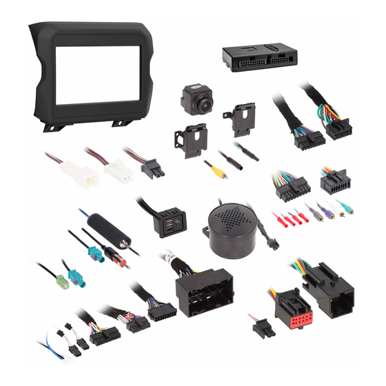
KIT COMPONENTS
• A) Radio bezel • B) Shallow mount brackets • C) Modular radio brackets • D) Panel clips (4)
A
AxxessInterfaces.com
Jeep Gladiator 2020-Up
Note: This kit will function in both Single-Zone and Dual-Zone vehicles.
Single-Zone vehicles will only get status feedback of the HVAC functions,
while Dual-Zone vehicles can also be controlled through the radio screen.
All HVAC functions will be retained. Compass is only retained on vehicles
equipped with the UConnect 3 (5" touchscreen). The External Speaker is
only required in vehicles with safety group features.
Attention! Designed for Pioneer's DMH-W4600NEX/WC4660NEX.
Pioneer 9" DMH-WC6600NEX will require minor custom mounting
along with the Metra 109-UN02 (sold separately)
B
C
D
© COPYRIGHT 2021 METRA ELECTRONICS CORPORATION
AXPIO-JT1
I N S T A L L A T I O N I N S T R U C T I O N S
TABLE OF CONTENTS
Dash Disassembly ..................................................2
Kit Assembly
- Radio provision ...................................................2
- Pioneer Modular DDIN radio provision ..............3
Axxess Interface Installation .................................4
WIRING & ANTENNA CONNECTIONS
Wiring Harness: Included with kit
Antenna Adapter: 40-EU10 • 40-GPS-PIO (included)
TOOLS & INSTALLATION ACCESSORIES REQUIRED
• Panel removal tool • Phillips screwdriver
Product Info
REV. 6/18/21 INSTAXPIO-JT1
Advertisement
Table of Contents

Related Manuals for Axxess AXPIO-JT1


Summary of Contents for Axxess AXPIO-JT1
- Page 1 - Pioneer Modular DDIN radio provision ....3 All HVAC functions will be retained. Compass is only retained on vehicles Axxess Interface Installation .........4 equipped with the UConnect 3 (5" touchscreen). The External Speaker is only required in vehicles with safety group features.
- Page 2 Metra recommends using 4. Remove (4) Phillips screws securing the the proper mating adapter from Metra radio, then unplug and remove. and/or Axxess. Test the radio for proper operation. (Figure A) 3. Place the radio into the dash, then secure using the factory screws.
- Page 3 Metra recommends using Note: Reference the installation manual the proper mating adapter from Metra provided with the radio for which and/or Axxess. Test the radio for proper hardware to use. The display screen and operation. radio chassis use two different types of screws.
-
Page 4: Table Of Contents
AXXESS INTERFACE INSTALLATION FEATURES TABLE OF CONTENTS • Provides accessory power (12-volt 10-amp) AXUSB-RAM1 Installation ......................5 • Retains R.A.P. (retained accessory power) Camera Removal ........................6-8 Assembly ............................9 • Provides NAV outputs (parking brake, reverse, speed sense) Wiring ............................10 • Allows visual of HVAC and gauges on Pioneer screen USB Replacement &... -
Page 5: Axusb-Ram1 Installation
AXUSB-RAM1 INSTALLATION 1. Remove the screw located above the window switches. Then with a panel tool, pop off the entire instrument panel trim from its retaining clips. (Figure A & B) 2. Disconnect the wiring harness connector, then unclip and remove the Media Hub from the backside of the panel. -
Page 6: Camera Removal
CAMERA REMOVAL 1. Remove the eight 5/32 bit screws from the tailgate panel. (Figure A) 2. Remove the panel and safely set aside. 3. Remove the two 5/32 bit screws from the smaller blue panel. (Figure B) 4. Remove the panel and safely set aside. NOTE: Some trucks that do not have a bed cover may look different. - Page 7 CAMERA REMOVAL (CONT) Unplug the pink camera cable and set aside. For this install the pink cable will not be used so iBEAM suggests ziptieing the cable back so there is no rattle in the tailgate. Remove the retention clip around the camera. Slide in the direction of the arrow and set aside, this will be needed this later when installing the new camera.
- Page 8 CAMERA REMOVAL (CONT.) 1. . This iBEAM kit covers the two options equipped on the Jeep Gladiator. • Figure A reverse or backup camera, The bracket with the number 1 is for the backup camera version. • Figure B surround view or 360, The bracket with the number 2 is for the surround view version.
-
Page 9: Assembly
ASSEMBLY Place the wire from the aftermarket camera through the hole between the numbers and the arrow. Keep the orienitation correct as to not mount the camera incorrectly. The top of the factory housing is the longer part of the housing. The top of the camera is indicated by the QC sticker and the top of the bracket is indicated by the arrow pointing towards the top of the... -
Page 10: Wiring
WIRING Re-assemble the camera into the tailgate. Run the wire, following the old camera wiring from the tailgate to the truck bed. (Figure A) Once inside the vehicle, you can power the camera via a reverse trigger from the taillight. Connect the RED wire to the reverse trigger. -
Page 11: Usb Replacement & Camera Installation
USB REPLACEMENT & CAMERA INSTALLATION • If power is required for the camera, the connection must be hardwired. If equipped with TPMS, and you wish to add the visual to the Pioneer Radio screen: • This can be done at the radio using the Red wire for power, and the Black wire for ground. • Route the LD-CAN3T harness behind the glovebox and connect to the junction pictured below. -
Page 12: Interface Installation
INTERFACE INSTALLATION If the vehicle is equipped with rear parking sensors that you wish to retain: • Connect the 40-GPS-PIO To the radio and to the GPS antenna in the vehicle. This can be Blue, or Yellow in color. • Install the provided speaker in the dash prior to assembling the radio components. Note: Alternatively, the GPS antenna supplied with the Pioneer radio can be used. -
Page 13: Dash Assembly
DASH ASSEMBLY Once all functions are verified: • Mount the radio into place using the (4) screws removed from dash disassembly. • Attached the supplied radio faceplate and secure it with two screws below the radio. • Snap the climate panel into the dash the same way it was removed. REV. -
Page 14: Radio Operation
RADIO OPERATION Vehicle Selection – Allows you to select the vehicle the radio is being installed in. Car Features – The source for accessing all vehicle information and options. • Vehicle type must be selected to activate menu & HVAC functions, as well as steering wheel controls. - Page 15 RADIO OPERATION (CONT) HVAC Operation – HVAC Status and Control Screen. Customizations Menu – Allows full control of vehicle personalization options. • Access this menu by selecting the gear icon on the previous screenshot. Vehicle Info Screen – Displays various information of the vehicle (TPMS, Park Position, Lights). About Screen –...
-
Page 16: Specifications
AXPIO-JT1 I N S T A L L A T I O N I N S T R U C T I O N S Having difficulties? We’re here to help. SPECIFICATIONS Contact our Tech Support line at: 386-257-1187 • RCA output for aftermarket radios or monitors...
Need help?
Do you have a question about the AXPIO-JT1 and is the answer not in the manual?
Questions and answers