Advertisement
Quick Links
4.Special comments
Even the most sophistic ated detcetors can some times be defeated or may fail to warn due to :DC power failure/improper connection, malicious mask-
ing of the lens,tampering with the optical system, decreased sensitivity in ambient temperatures near that of the human body and unexpected fail-
ure of a component part.The above list includes the most common reasons for failure recommended that the detector and the entire alarm system be ch-
ecked weekly, to ensure proper performance.An alarm system should not be regarded as a substitute for insurance. Home & property owners or renters sh-
ouldbe prudent enough to continue insuring their lives & property, even though they are protected by an alarm system.
This device has been tested and found to comply with the limits for a Class B digitaldevice, pursuant harmful interference in residential installations .This equipment
generates,us es and can radiate radio frequen cy energy and ,if not installed and used in accordance with the ins-tructions ,may cause harmful in-terference to radio and t-
elevision reception. However, there is no guarantee that interference will not occur in aparticular installation .If this device does cause such interference , which can be ver-
fied by turning the device off and on ,the user is encouraged to eliminate the interference by one or more of the followingmeasures:
- Increase the distance between the device and the receiver.
- Connect the device to an outlet on a circuit different from the one that supplies power to the receiver.
- Consult the dealer or an expericnced radio/TV technician.
WARNING! Changes or modifications to this unit not expressly approved by the party responsible for compliance could
void the user s authority to operate the equipment.
5 Solution of usual problem
In alarm area, have walk test but no alarm output
To open the detector
OK
Alarm LED lights up,
OK
cabin, check the relay
without alarm signal
contact is open or not
output
NG
Please contact us for Tech Support.
To check the detector
Alarm LED shut off,
OK
working voltage is at
without alarm signal
9-16V/DC or not
output
NG
To adjust the working voltage of
the detectorto 9-16 V/DC
False alarm
If there is strong cold or hot airflow in
Check the voltage of power
the detection area. such as from air
OK
supply. DC 9-16V
conditioner, heater, etc
If there is animal more than 20Kg in the
NG
detection area.
To adjust the power supply voltage
Installation height do not at 1.8-2.4m,.
to DC9-16V at certain redundancy.
Especially, less than 1.8m
The detector's sensitivity is too high
OK
Unstable installation base
If there is high voltage electric field near
NG
to the wire of detector
To select new installation base,
choose solid foundation
Wire terminal bad connected, with high
resistance
Output of power supply not good, not
good filtering
With electronic power on, no LED signal
NG
Check if the voltage is at
If the LED switch
Check the power
OK
DC9-16V or not, accord-
off or not
input connection
is correct or not
ing to the manual
OK
NG
Open the LED switch
Ensure power input
Check power supply
connection right
system at DC9-16V
Short circle or wrong earth conne-
OK
Disconnect the terminal to c-
ction in power supply, get rid of the
heck the power supply system
mistake
To check if the control main
To disconnect the alarm
OK
board faulty. If yes, contact
output wire from the terminal,
the supplier of mainboard.
check if there is short circuit
NG
Please clear the trouble of short-circuit
NG
OK
To reset the detector, check
OK
Repeat walk test
the LED lights up or not
OK
To get rid of cold or hot airflow, or cha-
nge installation environment.
To remove the over 20kg animal
To adjust installation height according
to the instruction
To adjust the sensitivity and repeat walk
test
To adjust the position of installation to
make sure it is far away from the high-
voltage electric field.
Wire terminal well connected
Change the power supply or repairing
OK
Please contact us for Tech Support.
To connect power supply
circle correctly
If the power supply
NG
OK
circle is open
The wire length of power
supply is exceeded, or wire
diameter is too small. Please
change into fitted wire.
NG
NG
Power supply system has problem,
need to be repaired or contact the
power system supplier
Installation Guide of
Outdoor Microwave & Infrared Motion Detector
1. Introduction
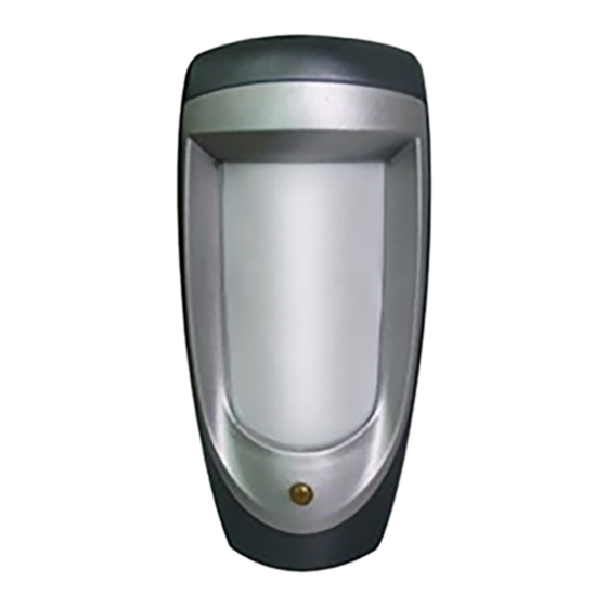
ZDD-285PIR is virtually the best outdoor/indoor motion detector ever presented, for industrial, commercial and res idential securi ty. ZDD-285PIR
has a m as sive aesthetic design and combines the technologies of passi ve infrared and Microwave as well It is waterproof and all-weather resistant.
ZDD-285PIR also alerts in any attempt to damage disable its operation . ZDD-285PIR combines a variety of detection techniques that enable it
to work in the most difficult environmental conditions and where high security is required while maint aining u nprece dented imm unity to false
alarms. The two synchr onized PIR sensors produce a three-dimensional thermal imaging of the protected area. Combining the fourt h dimension ad micr
owave scanning contributes to an amazing detection capacity and at the same time it also increases the reliability and immunity to false alarms. Using
this technique allows high sensitivity level adjustment in both detection technologies without the need of pulse count. In addition to an unpreceden t
-ed amazing and reliable detection skill, ZDD-285PIR is equipped with unique protection mechanisms against any attempt to damage or to disable
its operation. These following protection mechanisms always work-weather the alarm system is Armed or Disarmed:
1.Forntal Anti-mask ing by a continuous active inf rared scan, against masking the near field-of-view of the detector (Detects even transparent objects
such as clear glass, plastic bags or transparent spray of any king)
2. Imposes OR mode in distress. If from any reason, the PIR detection channel is neutralized(for example, the detector front was masked) the Micro-
wave detection channel will guard the protected area.
3.Anti-case-shifting, by inertial switch that alerts if someone shifts, moves or turns the detector.
2.Specifications
Top View
8
Models
6
ZDD-285PIR;
4
Detection Range:
12m
2
Input Voltage:9 to 16 VDC
0
Current Drain:About 65mA @ 12 VDC
2
4
PIR Section:Lens Date
6
NO.of Curtain Beams
8
(11+11+9)*2=62 (Typical)
Max.Coverage
1 *1 m /90
2
2
Tripping Indication:
Sise View
3 colour lights for about 30 seconds
cro w
2
Alarm ,Mask and Tamper
Alarm Output:
0
2
4
6
Solid-state relay, N.C & N.O up to 100mA/30V,-30
Tamper Contacts: N.C , 50mA resistive /30 VDC
Mask Output: N.C up to 100mA/30V,-30
3.Installation
3.1 General Guidelines
Don't face cold
Don't face the sun-
or heat directly
shine directly
3. 2Anti-pests installation
The upper part of the
Never face the detector to
detection area is non
the place that pests can
anti-pests area
climb up directly
ZDD-285PIR
Mounting
Surface or corner,at the height of 1.8 to 2.4 m
Note: Base allows single-sided corner mount at 45 to wall
Accessories:
BR-1:Surface mounted swivel bracket, adjustable 30
down and 45
left or right.
Environment:
Operating Temperature: -10 C to 50 C(14 F to 122 F )
Storage Temperature :-20 C to 60 C (-4 F to 40 F)
Anti white light :
9 0 0 0 LUX
Physical
Size(H*W*D):
176*83*66
m m
This device is coherent to Europe parliament direct 1999/5/EC
necessary items and rules, and also coherent to the main spirits
8 10 12m
of radio and telecom terminal equipments on March 9 . 1999.
The device also reaches the Canadian standard RSS-210. It can
be used indoor and outdoor, which can reach its maximum prote-
ction and avoidance of above interference.
Wire connection or
Don't install on a
detector can't be near
unstable base.
to high-pressure cable
Anti-pests weight
20Kg
The installation height
of the detector is 2.2-2.4
meters can Anti-pests
th
Don't face metal wall
Advertisement

Summary of Contents for ZUDSEC ZDD-285PIR
- Page 1 However, there is no guarantee that interference will not occur in aparticular installation .If this device does cause such interference , which can be ver- ZDD-285PIR also alerts in any attempt to damage disable its operation . ZDD-285PIR combines a variety of detection techniques that enable it fied by turning the device off and on ,the user is encouraged to eliminate the interference by one or more of the followingmeasures: - Increase the distance between the device and the receiver.
- Page 2 3.3Illustrated Installation Procedure 3.3.2 Mount base 3.9 Setting of detection angle 3.3.1 Disassemble unit A. Mark the drilling points 1.8-2.4m 6-8ft above ground E.Remove the PCB C.Move the cocer to the and drilling the wall D.Loose the screw volitant top and remove it When multi-function bracket B.
Need help?
Do you have a question about the ZDD-285PIR and is the answer not in the manual?
Questions and answers