
Subscribe to Our Youtube Channel
Related Manuals for Molecular Devices Digidata 1550

Summary of Contents for Molecular Devices Digidata 1550
- Page 1 Digidata® 1550 Low-Noise Data Acquisition System User Guide 5023399 A April 2013 www.moleculardevices.com...
- Page 2 For research use only. Not for use in diagnostic procedures. The trademarks mentioned herein are the property of Molecular Devices, LLC or their respective owners. These trademarks may not be used in any type of promotion or advertising without the prior written permission of Molecular Devices, LLC.
-
Page 3: Table Of Contents
Installing the pCLAMP Security Key (pCLAMP Only) ... . . 8 Installing the Digidata 1550 Digitizer......8 Configuring Software for Digidata 1550 Digitizer Use . - Page 4 Digidata 1550 Low-Noise Data Acquisition System User Guide Troubleshooting Problems and Solutions ..... 23 Isolating the Problem ........23 Power Light on the Front Panel Off .
-
Page 5: Chapter 1: Introduction
Clampex 10.4. AxoScope is an easy-to-use, full-featured data acquisition program for Windows that is included with the Digidata 1550 digitizer. The Digidata 1550 digitizer is contained within a rack-mount case, but it also has non-marking elastomeric feet for use on a desktop. Components •... -
Page 6: Minimum Computer Requirements
• 3 High-speed built-in USB 2 ports Programming The Digidata 1550 digitizer is supplied with the AxoScope 10.4 turnkey software for continuous data acquisition. No programming is required for use with this program, or with the pCLAMP 10.4 data acquisition software. -
Page 7: Chapter 2: Installation
Installing AxoScope or pCLAMP Software Note: Before installing the software from a CD-ROM, verify on the Molecular Devices support web site it contains the latest version. If you do not have the latest version, you can download it from the support web site www.moleculardevices.com/support. -
Page 8: Installing The Pclamp Security Key (Pclamp Only)
2. Attach the USB 2 cable to a USB 2.0 port on your computer, and then to the digitizer. 3. Switch on the power on the Digidata 1550 digitizer. 4. Let the Digidata 1550 digitizer warm up for one hour before performing experiments. 5. Windows automatically finds the new hardware and installs the drivers. - Page 9 Installation Figure 2-1: Example Digitizer Dialog. 3. In the Change Digitizer dialog select Digidata 1550 Series from the Digitizer Type list. Figure 2-2: Digitizer Type Selection of Digidata 1550 digitizer 4. Click the Scan button to detect the digitizer. The Configuration...
- Page 10 Figure 2-4: Digitizer dialog displaying active digitizer mode The Digitizer dialog appears showing the currently active digitizer mode. 6. Click OK to exit the Digitizer dialog. After the Digidata 1550 digitizer warms up (allow one hour), it is ready to perform experiments. 5023399 A...
-
Page 11: Chapter 3: Interface Description
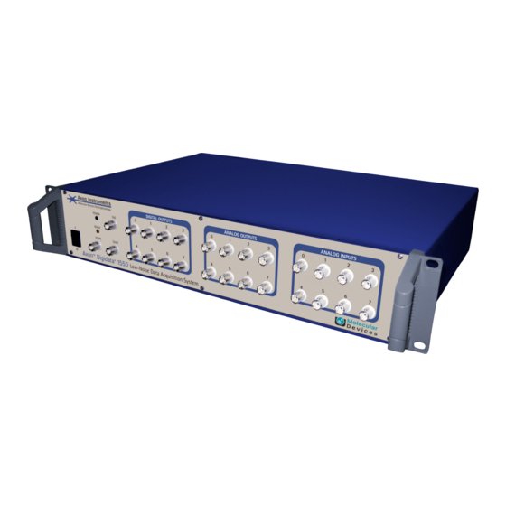
Interface Description Front Panel The following is the front panel description of the Digidata 1550 digitizer. Figure 3-1: Front panel of the Digidata 1550 digitizer. There is a single rocker-style On/Off switch. There are two indicator lights: POWER and READY. -
Page 12: Digital Outputs
Digidata 1550 Low-Noise Data Acquisition System User Guide Digital Outputs Digital Outputs 0–7 are on the front panel of the Digidata 1550 digitizer. These output levels can be set to high (+5 V) or low (0 V) TTL-level states. They can be used to trigger a wide variety of external devices. -
Page 13: Telegraph Inputs
Interface Description Telegraph Inputs The Digidata 1550 digitizer has a dedicated A/D converter that provides four telegraph input channels on the rear panel. These telegraph input channels provide gain, frequency, and capacitance values from manually-controlled amplifiers (for example, Axopatch 200B). These inputs are independent of the 8 analog input channels. - Page 14 Digidata 1550 Low-Noise Data Acquisition System User Guide 5023399 A...
-
Page 15: Chapter 4: Maintenance And Troubleshooting
• Troubleshooting Problems and Solutions on page 23 WARNING! Service or maintenance procedures other than those specified in this guide can be performed only by trained service engineers. When service is required, contact a Molecular Devices service engineer. 5023399 A... -
Page 16: Functional Checkout
The Functional Checkout procedure provides step-by-step instructions to verify signals. Step 1 If you are able to configure the Digidata 1550 digitizer in the software, then the digitizer is properly installed in Windows. To configure the digitizer for AxoScope or Clampex: 1. - Page 17 Click OK to exit this dialog. 3. Click the Configure button. 4. The Configure Digidata 1550 dialog displays the serial number of the device and the firmware version. The serial number should match the number on the barcode label of the unit.
-
Page 18: Step 2
Digidata 1550 Low-Noise Data Acquisition System User Guide Step 2 Check that you have a USB 2.0 port in your computer. 1. In Windows 7, right-click Computer and select Properties. In Windows XP, right-click My Computer and select Properties. 2. Click Device Manager. - Page 19 Maintenance and Troubleshooting 2. Set up a protocol through the Acquire > New Protocol menu command, and then on the Mode/Rate tab, select the Gap-free mode. On the Outputs tab, for each of the Analog OUT Channels, select the matching signal (for example, OUT 1) from its list.
-
Page 20: Step 4
Digidata 1550 Low-Noise Data Acquisition System User Guide Step 4 Verify analog inputs. With AxoScope or Clampex: Click the Lab Bench button (or click Configure > Lab Bench) and select the Input Signal tab. For each of the Digitizer Channels (for example, Analog IN #0), select a matching Signal (for example, IN 0), and configure that signal with unity scaling (for example, Scale factor (V/V): 1). -
Page 21: Grounding And Minimizing Noise
To avoid ground-loops, Molecular Devices recommends that you plug in the Digidata 1550 digitizer to the same power strip as the amplifier. Also, be aware that each Analog Input BNC on the Digidata 1550 digitizer is a single-ended input (all BNC shells are connected to signal ground). -
Page 22: Replacing Fuses
Molecular Devices. For Digidata 1550 digitizer fuse specifications, see AC Power on page The Digidata 1550 digitizer uses a pair of fuses located in a fuse carrier beneath the AC input connector (Figure 4-1). -
Page 23: Troubleshooting Problems And Solutions
Maintenance and Troubleshooting To replace the Digidata 1550 digitizer fuses: 1. Switch the power switch on the front of the instrument to the off position. 2. Unplug the power cord from the AC input connector. 3. Press the carrier-release side-tabs towards each other and then pull the fuse carrier to remove it from the instrument. -
Page 24: Power Light On The Front Panel Off
USB 2.0 cable to the computer. Ready Light on the Front Panel Flashes Continually The Digidata 1550 digitizer is in a problem state. Call Technical Support at Molecular Devices for a Work Order (WO) number before returning the unit for repairs. -
Page 25: Digitizer Does Not Work Properly
Maintenance and Troubleshooting Noise Introduced When Data Digitized • Verify that the acquisition software is not configured for a demo digitizer (Configure > Digitizer). Demo mode reproduces a command waveform with added noise (or generates artificial spike trains). • If noise is added to the signal on the analog input, make sure that all cables are routed away from switching power supplies, power cords, monitors, or any other major sources of noise. -
Page 26: Data Throughput Problems
In Configure > Program Options, select Disable screen saver during data acquisition. Contacting Support Check the Support section of the Molecular Devices website at www.moleculardevices.com/support where you will find a link to our on-line Knowledge Base that contains product-specific questions and answers to many common issues. - Page 27 1. Connect Analog Out 0 to Analog In 0. 2. Run an Episodic mode protocol with a waveform specified. 3. Click the View Only button. Do you see the waveform? Contact Molecular Devices Technical Support at support@moldev.com 1-800-635-5577 (USA only); elsewhere, contact your local representative.
- Page 28 Digidata 1550 Low-Noise Data Acquisition System User Guide 5023399 A...
-
Page 29: Appendix A: Specifications
Specifications This section lists electrical requirements, instrument dimensions, and space requirements for the Digidata 1550 Low-Noise Data Acquisition System. Analog Inputs Table A-1: Analog Inputs Input Name Description Number of channels Type of channels single-ended Resolution 16-bit, 1 in 65536... -
Page 30: Digital Inputs
Digidata 1550 Low-Noise Data Acquisition System User Guide Table A-2: Analog Outputs (cont’d) Output Name Description Output short circuit to signal ground ±25 mA Digital Inputs Table A-3: Digital Inputs Input Name Description Input type 5V nominal, >4V high threshold... -
Page 31: Telegraph Inputs
Specifications Table A-5: Pin Assignments (cont’d) Pin number Digital Output Analog ground Internal Use (or 14) Analog ground Analog ground Analog ground Analog ground Analog ground Internal Use (or 13) Scope Output (or 15) Analog ground Pin 24 is configured as the front panel SCOPE output, using the hardware’s 16th digital bit (15). -
Page 32: Ac Power
Digidata 1550 Low-Noise Data Acquisition System User Guide AC Power The AC Power is supplied from a single AC input connector on the rear panel for the supplied AC power line cord. Table A-7: AC Power Voltage Description Voltage input rating for 1550 100 V–240 V AC, 50/60 Hz... -
Page 33: Appendix B: Electromagnetic Compatibility (Emc)
Electromagnetic Compatibility (EMC) REGULATORY INFORMATION FOR CANADA (ICES/NMB-001:2006) This ISM device complies with Canadian ICES-001. Cet appareil ISM est confomre à la norme NMB-001 du Canada. ISM EQUIPMENT CLASSIFICATION (Group 1, Class A) This equipment is designated as scientific equipment for laboratory use that intentionally generate and/or use conductively coupled radio- frequency energy for internal functioning, and are suitable for use in all establishments, other than domestic and those directly connected to a... - Page 34 Digidata 1550 Low-Noise Data Acquisition System User Guide In order to maintain compliance with FCC regulations, shielded cables must be used with this equipment. Operation with non-approved equipment or unshielded cables is likely to result in interference to radio and TV reception. The user is cautioned that changes and modifications made to the equipment without the approval of the manufacturer could void the user's authority to operate this equipment.
-
Page 35: Appendix C: Safety Guide
WARNING! If the Digidata 1550 Low-Noise Data Acquisition System is used in a manner not specified by Molecular Devices, the protection provided by the equipment may be impaired. -
Page 36: Instrument Safety Labels
Digidata 1550 Low-Noise Data Acquisition System User Guide Instrument Safety Labels Safety labels are located on the instrument. Each Safety label consists of • Signal Word panel, which implies a particular level of observation or action (for example, CAUTION or WARNING). If a safety label encompasses multiple hazards, the Signal Word corresponding to the greatest hazard is used. -
Page 37: Index
Index analog input 11 installation 7 analog output 11 interface description 11 front panel 11 AxoScope 5 rear panel 12 introduction 5 components 5 minimum computer requirements Clampex 5 recommended computer system digital output 12 power supply 13 electromagnetic compatibility 33 EMC 33 specifications 29 ground 25... - Page 38 Digidata 1550 Low-Noise Data Acquisition System User Guide troubleshooting 15 before you call 26 functional checkout 16 grounding and minimizing noise 5023399 A...
Need help?
Do you have a question about the Digidata 1550 and is the answer not in the manual?
Questions and answers