Advertisement
Table of Contents
- 1 Kit Contents
- 2 Required Parts Not Supplied in the Kit
- 3 Part 1: Connecting the Driver Card to the Display
- 4 Connect the Driver Card to the Power Supply and HDMI Source
- 5 Part 2: Connecting the Touch Panel
- 6 Further Information
- 7 About IDS
- 8 Intelligent Group Solutions Divisions
- Download this manual
Kit Content
Required Parts not Supplied in Kit
+44 (0)1635 294600 | info@i-lcd.com | www.i-lcd.com
Intelligent Display Solutions, Unit 2, Berkshire Business Centre,
Berkshire Drive, Thatcham, Berkshire, RG19 4EW
A division of Intelligent Group Solutions Ltd
Quick Start Guide
AM-1024768Z3TZQW-TH0H
CONTENTS
page 2
Part 1: Connecting the driver card to the display
page 2
Part 2: Connecting the touch panel
© IGS Version V1
page 3
page 5
1 of 8
Advertisement
Table of Contents

Related Manuals for IDS AM-1024768Z3TZQW-TH0H


Summary of Contents for IDS AM-1024768Z3TZQW-TH0H
- Page 1 © IGS Version V1 Quick Start Guide AM-1024768Z3TZQW-TH0H CONTENTS Kit Content page 2 Part 1: Connecting the driver card to the display page 3 Required Parts not Supplied in Kit page 2 Part 2: Connecting the touch panel page 5 +44 (0)1635 294600 | info@i-lcd.com | www.i-lcd.com...
- Page 2 © IGS Version V1 KIT CONTENTS Item Description Display with touch panel Driver card USB adapter card REQUIRED PARTS NOT SUPPLIED IN THE KIT Item Description RS Part Number 12V 2A Power supply with 2.1mm x 5.5mm DC Jack 144-0971 Generic USB mini lead 193-2871 Generic HDMI cable...
- Page 3 © IGS Version V1 PART 1: CONNECTING THE DRIVER CARD TO THE DISPLAY Connect the LVDS connector from the driver card to the back of the LCD. Take care to line up the pins and use the correct orientation as per the picture below. Connect the backlight connector from the driver card to the back of the LCD Take care to line up the pins and use the correct orientation as per the picture below The connections should look like this...
- Page 4 © IGS Version V1 CONNECT THE DRIVER CARD TO THE POWER SUPPLY AND HDMI SOURCE Connect the power connector to the 12V DC power supply using a 2.1mm connector with centre positive and barrel negative Connect the HDMI connector to your source. Turn the power switch to the ON position +44 (0)1635 294600 | info@i-lcd.com | www.i-lcd.com Intelligent Display Solutions, Unit 2, Berkshire Business Centre,...
- Page 5 © IGS Version V1 PART 2: CONNECTING THE TOUCH PANEL The display has an FFC tail with the USB Connections. Remove any packing foam and tape to release the Touch control board from the back of the display. Place the display face up and line up the small USB connector PCB. +44 (0)1635 294600 | info@i-lcd.com | www.i-lcd.com Intelligent Display Solutions, Unit 2, Berkshire Business Centre, Berkshire Drive, Thatcham, Berkshire, RG19 4EW...
- Page 6 © IGS Version V1 PART 2: CONNECTING THE TOUCH PANEL Locate CN4 on the PCB and carefully lift up the flap. Note the orientation of the FFC and the PCB, it must be connected the correct way round or damage may occur. Push the FFC tail into the connector far enough so that the dark strengthening section is all the way in, and close the flap.
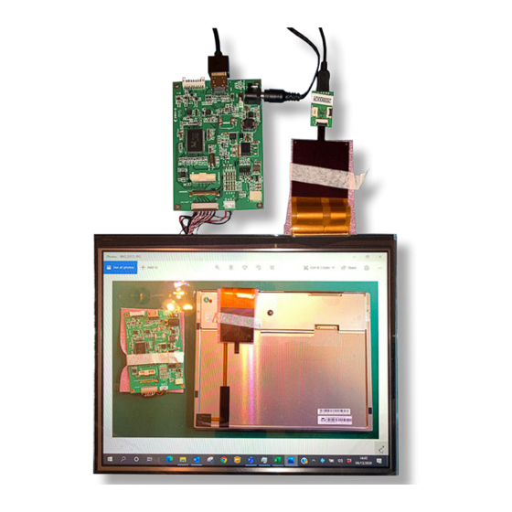
- Page 7 © IGS Version V1 PART 2: CONNECTING THE TOUCH PANEL Insert the USB mini connector into the adapter board and connect to your PC. The touch screen will be automatically recognised and installed by Windows 10. Warning: The FFC is very fragile and if the USB cable is caught it is likely to cause permanent damage by tearing the flexible PCB. It is recommended that the USB cable and adapter PCB are secured to the back of the display using adhesive tape to stop any strain on the connections.
- Page 8 The values contained in this data sheet can change due to technical innovation. Any such changes will be made without separate notification. If you require further assistance or have a specific or custom enquiry, please contact the IDS team via email or phone. Alternatively please visit our website for more product info and to see our full range.
Need help?
Do you have a question about the AM-1024768Z3TZQW-TH0H and is the answer not in the manual?
Questions and answers