Table of Contents
Advertisement
Quick Links
Advertisement
Table of Contents

Subscribe to Our Youtube Channel
Related Manuals for Colorjet Metro Konica Head


Summary of Contents for Colorjet Metro Konica Head
- Page 2 Disclaimer The information and instructions provided in this user manual have been checked for accuracy, uniqueness, and reliability. ColorJet group reserves all the rights to modify and revise this manual as per the company requirements without any prior notice. “No part of this document shall be reproduced or used by externals without prior permission of the ColorJet group”.
-
Page 3: Table Of Contents
Table of Contents 1. About Document ............................5 Purpose ..............................5 Intended Audience ............................ 5 2. Machine Specification ..........................5 3. Machine Overview ............................ 6 Front View ..............................6 Back View ..............................7 Front and Back Views of Feeder ....................... 8 Front and Back Views of Dryer ........................ - Page 4 Feeding Password ........................... 33 8. Printer Software Operations ........................35 Setting the Print Origin ........................... 35 Print Head Calibration ..........................36 Opening the Calibrating Wizard ......................36 Horizontal Calibration ......................... 37 Step Calibration ........................... 39 Setting Print Parameters ......................... 40 Adding Jobs .............................
- Page 5 14 Troubleshooting ............................. 58 Printer Not Initializing ..........................58 Jetting Pump Not Working ........................58 Water Seepage in Belt ..........................58 Belt Shifted .............................. 58 Negative Pressure Drop/Not Working ....................58 Fabric Not Sticking to Belt ........................58 Print Not Drying/Ink Marks on Back of the Fabric .................. 58 Ink Not Filling ............................
-
Page 6: About Document
Infrared Heaters Operating Interface Touch screen Printing Interface USB 3.1 RIP Software Supported ErgoSoft / NeoStampa (Colorjet Editions) File Format JPEG, TIFF, BMP/PDF (RGB, CMYK) Power Supply 220 V, 80 A Single/Three phase load distribution, 50Hz, Operating Conditions Temperature 18 to 28 C, Humidity: 35-80% RH ( Non-... -
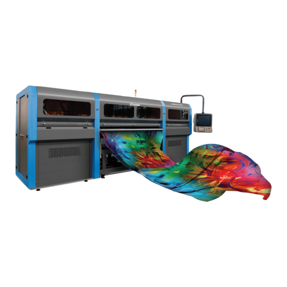
Page 7: Machine Overview
3. Machine Overview Front View The Front View of the machine is shown in the image below: Fig 1: Displaying the Front View of the Machine Table 1: Different Part of the Printer 1. Left Cover 2. Front Cover 3. Signal Lamp 4. -
Page 8: Back View
Back View The Back View of the machine is shown in the image below: Fig 2: Displaying the Back View of the Machine Table 2: Different Part of the Printer 1. Emergency Button 2. Ink Tanks 3. Ink Inlet 4. Pressure Roller 5. -
Page 9: Front And Back Views Of Feeder
Front and Back Views of Feeder The Front Side of the Feeder is shown in the image below: Fig 3: Displaying the Front View of the Feeder Table 3: Different Part of the Printer 1. Fabric Spreading Roller 2. Supply Air Shaft 3. - Page 10 The Back Side of the Feeder is shown in the image below: Fig 4: Displaying the Back View of the Feeder Table 4: Different Part of the Printer 1. Fabric Spreading Roller 2. Power Control Unit 3. Supply Motor 4. Leveler 5.
-
Page 11: Front And Back Views Of Dryer
Front and Back Views of Dryer The Front Side of the Dryer is shown in the image below: Fig 5: Displaying the Front View of the Dryer Table 5: Different Part of the Printer 1. Guiding Bar 2. Guiding Bar 3. - Page 12 The back side of the Dryer is shown in the image below: Fig 6: Displaying the Back View of the Dryer Table 6: Different Part of the Printer 1. Exhaust Fuel 2. IR Heater 3. Guiding Bar 4. MCB Heater 1 5.
-
Page 13: Getting Ready For Printing
4. Getting Ready for Printing Switch ON Procedure Follow these steps to switch ON the printer: Step 1: Switch ON the MCB from back side of the machine. Step 2: Check whether an Emergency button is pressed or not. If the Emergency button is pressed, then immediately release it. -
Page 14: Signal Lamp Description
Step 15: Check whether Jetting and Brush Roller working properly or not. Step 16: Rip the image file using the Ripping software provided with the machine. Step 17: Set the print origin to specify the printing starting position. Now, the printer is ready for printing. Signal Lamp Description Signal Lamp description is given as below: Color... -
Page 15: Loading The Fabric
Loading the Fabric Follow these steps to load the fabric: Step 1: Run the Supply Motor in the manual. Step 2: Stop the Supply Motor when the unlock position of Safety Chuk and Shaft get matched, as shown below: Unlock Position Fig 9: Displaying the Unlock Position Unlock Position Step 3: Push the Safety Chuk to remove the shaft. - Page 16 Step 6: Load the media as per the path given below: Fig 11: Displaying the Fabric Path Now, the fabric gets loaded. Metro (Konica Head) Page 15 of 62...
-
Page 17: Filling Ink
Filling Ink To refill ink, remove the Main Ink Tank cap and refill ink as per the color sticker. The Main Ink Tank is shown in the image below: Main Tank Cap Fig 12: Displaying the Main Ink Tank Points need to remember: •... -
Page 18: Glue Coating
5. Glue Coating Glue Implementation Glue is composed of three different chemicals and two solvents. Chemicals: • Prima: It is used as a primitive coat, for smoothening the belt surface. This is to be done only when the previous glue layers have been washed completely. •... - Page 19 Note: Actual consumption depends on the work load, fabric type, and the maintenance. Generally, shelf life for these chemicals is approx. 4 years. Shelf life for this chemical are approx. 4 years. Some of the Glue are having these chemicals as base and it harms the belt or adversely affects the life of the Printing Blanket (Conveyor Belt): RECOMMENDED •...
-
Page 20: Glue Process Preparation
Glue Process Preparation Follow these steps for glue process preparation: Step 1: Keep the ventilators and exhaust fans ready. Step 2: Lift up the Press Roller and remove the fabric, if any. Step 3: Run the Wash Cycle from HMI, simultaneously belt can be cleaned by wiping with cloth. Fig 14: Running the Wash Cycle Step 4: Put masking PVC tape on both edges of the Conveyor Belt, by simultaneously moving the belt through HMI in slow speed. -
Page 21: Glue Coating Procedure
Step 5: Put on gloves, goggles, and face mask for safety Fig 16: Using Safety Precautions Step 6: Keep ready the following items:- • Glue container(500-600ml), whichever required • Home cleaner liquid spray • Pouring container • Waste bin • Woven cotton bud sticks (for spreading the glue) Glue Coating Procedure Note: Extreme care to be taken during the glue process, any negligence may render the coat unsuitable... - Page 22 Step 5: Once the glue has crossed the press roller, speed can be increased to 20. Using the cotton bud stick, keep spreading the glue from the area where glue is in excess, to the area wherever the glue is less in quantity.
-
Page 23: Glue Removing Preparation
Step 11: Once excess glue is removed, run glue cycle for 30-50 min with glue dryer on. Step 12: Wipe off the glue from the Press Roller, with the help of cleaner damp towel. While cleaning the Press Roller, cover the belt surface with poly sheet to avoid the glue remains falling on the belt surface. - Page 24 Step 3: Pour cleaner liquid (Solvtek) onto wipe clothes. Fig 21: Pouring Cleaner Liquid Step 4: Wait 5 minutes to dissolve glue. Step 5: Wipe dissolved glue and cleaner by wipe clothes. Step 6: After wiping out the part, turn the belt and repeat wiping until wipe out over all. Fig 22: Wiping the Glue Step 7: Spray or pour purified water onto the belt.
- Page 25 Step 9: After clean up the part, turn belt and repeat cleaning until clean up over all. Remove cover sheet which covers washing unit. Step 10: Finally, remove remained cover sheets, and keep the belt dry. Fig 24: Removing the Cover Sheet Metro (Konica Head) Page 24 of 62...
-
Page 26: Control Panel Operations (Hmi)
6. Control Panel Operations (HMI) Main Menu After the Start Up screen, the MAIN MENU screen appears with a list of options, as shown below: Fig 25: Displaying the Main Menu Screen The description of different options in the MAIN MENU screen is given as follow: •... -
Page 27: Enabling Or Disabling Services
For purging, touch each color button for few seconds and then, wipe extra ink using the cloth issue. Enabling or Disabling Services User can enable or disable Print Engine, Negative Control, and Ink Valve by touching the Service button on the MAIN MENU (Refer to Fig 25). The SERVICE screen is shown in the image below: Fig 27: Displaying the SERVICE Screen Touch on the service which you want to disable (Refer to Fig 27). -
Page 28: Setting Belt Speed
Setting Belt Speed To set the belt speed, select the SPEED icon from the BELT MOOVEMENT screen. The Numeric Keypad appears on the BELT MOVEMENT screen, as shown below: Fig 29: Setting the Belt Speed Now, enter the belt speed in the Numeric Keypad and select the Enter button to set the belt speed. Setting Washing Unit To set the position of washing tub, select the TUB DOWN icon from the WASHING SYSTEM screen. -
Page 29: Controlling Dryers Settings
Controlling Dryers Settings To change or update the dryer settings, select the READY TO PRINT button from the MAIN MENU screen (Refer to Fig 25). The READY TO PRINT screen appears as shown below: Fig 31: Displaying the HEATERS SETTINGS Screen Using the above screen, change the washing system, switch ON or OFF FEEDER and SPREADER ROLLER, and print dryer settings. -
Page 30: Online Mode
ONLINE Mode Using the ONLINE mode, user can directly issue the print command, stop the print, resume the print, and start the print from beginning. On touching the ONLINE icon, the following screen appears: Fig 33: Displaying the ONLINE Mode Screen To go directly to the READY TO PRINT screen, touch on the Ready To Print icon. -
Page 31: Getting Familiar With Printer Manager Interface
7. Getting Familiar with Printer Manager Interface The User Interface of the Printer Manager software is shown as below: Quick Access Toolbar System Status Print Parameters Job Preview Job Information Job List Error Information Fig 34: Displaying the User Interface of the Printer Manager Main Menu The description of the Printer Manager window is given as below: •... -
Page 32: Setting Menu
Setting Menu The Setting window with the Printer tab is shown in the below image: Fig 35: Displaying the Setting Window Metro (Konica Head) Page 31 of 62... - Page 33 The Move tab is shown in the image below: Fig 36: Displaying the Move Tab The Preference Tab is shown in the image below: Fig 37: Displaying the Preference Tab Note: Unit value can be changed using the Unit drop down list. Metro (Konica Head) Page 32 of 62...
-
Page 34: Feeding Password
The Calibration tab is shown in the image below: Fig 38: Displaying the Calibration Wizard Feeding Password The Password option enables operator to feed password of the printer. On clicking Password option under the Tools menu, the Password window appears with two options viz. Time Password and Language Password. - Page 35 The Password window appears on the screen as shown below: Fig 40: The Password Window Step 2: Set values in the Time Password field as per the requirements (Refer to Fig 40). Note: The length of the password field must be of 16 digits. Step 3: After feeding the passwords, click on the Set button in front of both the options (Refer to Fig 40).
-
Page 36: Printer Software Operations
8. Printer Software Operations Setting the Print Origin Print origin sets the print starting point with the left limit switch as the reference point. It can be set by two ways; moving and positioning the carriage and typing the offset value directly in the given field. Follow these steps to change the print origin: Step 1: Move the carriage at the position from where you want to start the printing by clicking on the left and right buttons on the Quick Access Toolbar, as shown below:... -
Page 37: Print Head Calibration
Print Head Calibration The Print Head calibration is categorized into the following types: • Mechanical Check: Includes Vertical Check and Angle Check • Software Calibration: Includes Horizontal Calibration and Step Calibration Let’s discuss the above-mentioned checks and calibration one by one in details. Note: Mechanical checks are performed by service engineer, thus these checks and their description are not included in user manual. -
Page 38: Horizontal Calibration
When you press the Next button, we redirect to the software calibration screen, as shown in the below images: Fig 47: Displaying the Printer Calibration Options Horizontal Calibration Horizontal Calibration checks the bi-directional, left, and right alignment and corrects it by adding or subtracting the correction value from the default set value. - Page 39 The Bi-direction Calibration result is shown in the image below: Fig 48: The Bi-Direction Calibration Output Based on the above figure, you can notice that the Bi-direction calibration is good at “0” position. The correction value is “0” which means you need not to correct the bi-direction value. Sometimes, the correction value can either positive or negative.
-
Page 40: Step Calibration
The Left Calibration Result is shown in the image below: Left Check Fig 49: The Horizontal Left and Right Checks Right Check Step Calibration The printer step calibration is performed to verify and correct fabric feeding. The printer prints a complete image pass by pass. -
Page 41: Setting Print Parameters
From the above figure, you get the accurate step adjust correction value. The correction value is either positive or negative. If the value is positive, then add it in the current step adjust value for the Print Head calibration. On the other hand, if the value is negative, then subtract the value from the current step adjust value. -
Page 42: Adding Jobs
Adding Jobs There are two ways to add jobs in the Job List area viz. the Add Job button and right click on the Job List area. Let’s discuss both the ways one by one. Follow these steps to add jobs in the Job List area: Step 1: Click on the Add Job button on the Quick Access Toolbar, as shown below: Fig 53: Clicking on the Add Job Button The Open window appears on the screen. - Page 43 Now, the selected image appears in the Job List area, as shown below: Fig 55: Displaying the Added Job and Their Details Once a file has been added its information such as file path, size, resolution, and number of passes can be viewed in the Job Information area.
-
Page 44: Editing Job
Editing Job Follow these steps to edit the selected job: Step 1: Select the job for which details you want to edit from the Job List area. Step 2: Right-click on the selected job. The context menu appears on the screen. Step 3: Select on the Edit option from the context menu, as shown below: Fig 57: Selecting the Edit Job Option The Edit Job Form appears with the list of options viz. -
Page 45: Ripping And Printing
Similarly, you can click on any other option and its related options get enabled in the right pane of the Edit Job form. Ripping and Printing Ripping is an independent process which converts a raw image file into the machine-readable format and get the file ready for printing. -
Page 46: Dpi And Mode
After issuing the Print command, the printing gets started and its progress details displays in the Job Information area, as shown below: Fig 61: Displaying the Printing Details DPI and Mode There are different combination of print modes and resources, as shown through the table: Print DPI Print Passes 600x600... -
Page 47: Head Cleaning
9. Head Cleaning Print Head is a delicate part which needs to be cleaned as per the recommended methods to have long life and to ensure consistent print quality. Below sections give recommended steps to clean the Print Heads. Head Blotting Head blotting refers to the process in which the head surface area is cleaned for better printing result and quality. -
Page 48: Setting Wiping And Capping Height
• Wiper Pos: Define the wiper position. • Capping Enable: Enable the auto capping functionality. • Auto Capping Time: Define the auto capping time. When the printer is ideal for the define time then auto capping process gets started and capped the capping station with the head plate. Setting Wiping and Capping Height Using the Setting window, user can set the wipping and capping height by updating values in the Z Clean Pos and Z Wet Pos list boxes, as shown below:... -
Page 49: Head Spraying
Head Spraying Head spraying should be performed only when small percentage of nozzles are blocked. This method is used to avoid mixing of colors. When heads are sprayed all the nozzles are actuated at a high rate which helps in opening up dry nozzles of the printer. To perform head spraying, click on the Spray button available under the Quick Access Toolbar, as shown below: Fig 67: Displaying the Spray Button Metro (Konica Head) -
Page 50: Cleaning Tub Unit
10. Cleaning Tub Unit Cleaning Tub Unit Follow these steps to clean the tub unit: Step 1: Lower down the tub using HMI and follow the below path: Main Menu Ready To PrintWashing System Tub Out, as shown below: Fig 68: Issuing the Tub Out Command Step 2: Loose Allen screws from both sides to remove the tub, as shown below: Fig 69: Loosing Allen Screws Metro (Konica Head) - Page 51 Now, the tub comes out and user can start the maintenance work, as shown below: Brush Sponge Roller Fig 70: Cleaning Tub After completing the cleaning, reversely follow the above given steps to fix the tub. Metro (Konica Head) Page 50 of 62...
-
Page 52: Cleaning Jetting Nozzle
Cleaning Jetting Nozzle Jetting Nozzles are shown as below: Jetting Nozzles Fig 71: Displaying the Jetting Nozzles To clean jetting nozzles, remove them using the 10mm spanner and clean it to remove any block. Metro (Konica Head) Page 51 of 62... -
Page 53: Switch Off Procedure
11. Switch OFF Procedure Note: Main MCB power must be ON. Follow these steps to learn the switch off procedure: Step 1: Perform the Nozzle Test to check Print Head nozzles status. Step 2: Clean the Print Heads, if required. Step 3: Remove the media from the machine. -
Page 54: Do's And Don't
12. Do’s and Don’t Do’s 1. Keep the room dust free and maintain the temperature between 25°C and 28°C 2. Water filter plates should be fitted when jetting pump is on 3. Always care about the wrinkles on fabric, it may damage the Print Heads 4. -
Page 55: Maintenance
13. Maintenance Print Head Maintenance Print Head is an important and delicate part of the printer. Thus, it must be handled with care to ensure the long life of the Print Heads. For Print Head maintenance, the following instructions should be taken care: •... -
Page 56: Belt Shifting Control
a) Wait for the completion of the current printing process. If the print command repeats, then immediately stop giving the next print command for printing. b) Takeout the fabric, lower down the tub, and run glue cycle in reverse direction with the 70% speed. -
Page 57: Weekly Maintenance
• Press roller and fabric guiding rollers should be wiped daily to remove the ink stains. Precautions: • While Print engine off and capping elevated, never move the carriage over the capping station • Always pour distill water in the Capping tray to avoid germs Weekly Maintenance Washing Tub Maintenance Washing Tub is an integral part of the Printer. -
Page 58: Monthly Maintenance
Computer Storage Management: • Remove unwanted files from your computer to maintain a minimum of 10GB free space in hard disk. • Remove unwanted programs and old ripped files from the computer to improve the speed of printing. Monthly Maintenance •... - Page 59 14. Troubleshooting Printer Not Initializing • Emergency button is pressed • Capping unit is in up position • Print engine is OFF • Main Board is faulty • Encoder sensor is not connected to HB • Limit switch is disconnected from MB Jetting Pump Not Working •...
- Page 60 • Coating of fabric is not correct • Fabric supporting bar and Take Up roller is stained with ink Ink Not Filling • Main tank is empty • Ink pipe is having cut/bend • Ink pump is not working/connector loose/open •...
- Page 61 Lines in Prints • Nozzle blocked in heads (check nozzle test) • Incorrect feed step (calibration required) • Belt motor coupling loose Metro (Konica Head) Page 60 of 62...
- Page 63 For Any Query Please Contact Us www.colorjetgroup.com Call us on +91-120-4548195 Email on info@colorjetgroup.com For Ink Enquiry:- sales@colorjetgroup.com...
Need help?
Do you have a question about the Metro Konica Head and is the answer not in the manual?
Questions and answers