Table of Contents
Advertisement
Quick Links
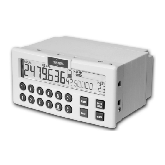
N413-P
BATCH-CONTROLLER
WITH NUMERICAL KEYPAD and RECEIPT PRINTER DRIVER
Signal input flowmeter: Pulse – Coil, NPN, PNP, Reed, Namur, Active
Control input:
Five inputs for remote control.
Control output:
Five outputs to control valves, pumps and alarms
Communication: Printer interface for receipt printing
Save time and cost with the user-friendly N413 batch controller.
More info: www.fluidwell.com/nseries
Advertisement
Table of Contents

Related Manuals for Fluidwell N Series


Summary of Contents for Fluidwell N Series
- Page 1 Signal input flowmeter: Pulse – Coil, NPN, PNP, Reed, Namur, Active Control input: Five inputs for remote control. Control output: Five outputs to control valves, pumps and alarms Communication: Printer interface for receipt printing Save time and cost with the user-friendly N413 batch controller. More info: www.fluidwell.com/nseries...
- Page 2 Page 2 FW-N413-P-M_v0204_01_EN.docx...
-
Page 3: Disclaimer
Page 3 DISCLAIMER • The information contained in this document is subject to change without notice. The manufacturer makes no representations or warranties with respect to the contents hereof and specifically disclaim any implied warranties of merchantability or fitness for a particular purpose. •... -
Page 4: Intended Use
▪ appointed for the certification, the occupational, health, safety and the quality tasks. WARRANTY AND TECHNICAL SUPPORT For warranty and technical support for your Fluidwell products, visit our internet site www.fluidwell.com or contact us at support@fluidwell.com. -
Page 5: About The Operation Manual
Firmware version: 03.06.xx Manual: FW-N413-P-M_v0204_01_EN.docx © Copyright 2018: Fluidwell B.V. - The Netherlands. Information in this manual is subject to change without prior notice. The manufacturer is not responsible for mistakes in this material or for incidental damage caused as a direct or indirect result of the delivery, performance or use of this material. -
Page 6: Table Of Contents
Page 6 CONTENTS MANUAL Disclaimer ........................... 3 Safety instructions ........................3 Federal Communications Committee (FCC) ................3 Disposal - WEEE Directive ......................3 Safety rules and precautionary measures .................. 3 Intended use ..........................4 UnIntended use .......................... 4 Target group ..........................4 Warranty and technical support .................... -
Page 7: Introduction
Page 7 INTRODUCTION 1.1. SYSTEM DESCRIPTION OF THE N413-P Functions and features The batch controller model N413-P is a microprocessor driven instrument designed for batching and filling of small and large batch size quantities. This product has been designed with a focus on: ▪... - Page 8 Below example shows a printed receipt. The arrows indicate the items that can be configured. For configuration details and options see chapter 4. 4 configurable headers ==================== FLUIDWELL F132P Timestamp upon -------------------- batch delivery Date: 01/01/10...
- Page 9 Page 9 Display information The unit has a large LCD with a bright LED backlight and displays all kinds of symbols, digits and measuring units, status information and key-word messages. P R O G S T A R T E N T ER H O L D R E S E T R AT E...
-
Page 10: Operational
Page 10 OPERATIONAL 2.1. GENERAL ▪ The N413-P may only be operated by authorized and trained personnel. ▪ All instructions in this manual are to be observed. ▪ Take careful notice of the "Safety rules, instructions and precautionary measures" in the front of this manual. -
Page 11: Operator Information And Functions
Page 11 2.3. OPERATOR INFORMATION AND FUNCTIONS In general, the N413-P will always function at Operator level. The information displayed and the functional keys available are dependent upon the SETUP-settings and the active function. NOTE: If the key-sign is displayed, FW-4100-000014-001-EN the particular key(s) or functions are not accessible! ▪... - Page 12 Page 12 ID Number (Only available if enabled). It might be that an ID number (e.g. customer, driver, tank, …) will be asked before a batch can be started. This numeric value can be entered immediately. By pressing the START-key (or by activating external control ‘START’), the entered value will be accepted and the batch started immediately.
-
Page 13: Operator Alarms
Page 13 ▪ Clear total Total can only be reset if no batch process is active (status: READY). This function might not be available due to configuration settings. The value for total can be re-initialized. To do so, select Total and press RESET: the flashing text "PUSH RESET"... -
Page 14: Installation
Page 14 INSTALLATION 3.1. GENERAL DIRECTIONS • Installation, electrical wiring, start-up and maintenance of this instrument may only be carried out by authorized and trained personnel. Personnel must read and understand this Instruction Manual before carrying out any work. • The N413-P may only be operated by personnel who are authorized and trained by the operator of the facility. -
Page 15: Installation / Surrounding Conditions
Page 15 3.2.2. INSTALLATION / SURROUNDING CONDITIONS Take the relevant IP classification of the enclosure into account (see manufactures plate). Even with an IP67 (Type 4X) enclosure, the unit should not be exposed to harsh unnecessary harsh weather conditions. When used in extreme cold surroundings or varying climatic conditions, take the necessary precautions against moisture by placing a dry sachet of silica gel, for example, inside the control cabinet. -
Page 16: Install The Unit Into The Cabinet (Panel)
Page 16 3.2.4. INSTALL THE UNIT INTO THE CABINET (PANEL) 1. Install the screws in the clamps (1, 3, 4, 7). 2. Install the gasket onto the unit (2). 3. Put the unit (2) in the correct position for installation. 4. -
Page 17: Terminal Connectors
Page 17 Cable and wire selection The unit complies with the Directives and Standards for Electro Magnetic Interference. For a reliable signal transfer and prevention of external signal interference (crosstalk), for signal wiring, the recommendation is made for a shielded (twisted pair) cable which meets at least the Category 5 cable standard. - Page 18 Page 18 Sine-wave signal (Coil): The N413-P can be connected to flowmeters that have a coil output signal. With SETUP 6.1 two sensitivity levels can be selected: • COIL LO: sensitivity from about 120mVp-p. • COIL HI: sensitivity from about 20mVp-p Figure 14: Terminal connections - Coil signal input (typical) Reed-switch: The N413-P is suitable for use with flowmeters which have a reed-switch.
- Page 19 Page 19 Pulse-signal NPN / NPN LP: The N413-P is suitable for use with sensors which have a NPN output signal. For reliable pulse detection, the pulse amplitude has to go above 1.2V. Signal setting NPN-LP employs a low-pass signal noise filter, which limits the maximum input frequency - read par. 4.2.8. Figure 17: Terminal connections - NPN signal input (typical) Active signal: If a sensor gives an active signal (read chapter 3).
- Page 20 Page 20 Terminal 8 - 9; External control - Start With this function, the batch controller can be STARTED remotely. The input must be switched with a potential free contact to the GND-terminal number 8 for at least 100msec. Note: in case the function “ID” is enabled (setup 5.5), external start must be switched twice to start a batch! Figure 20: Terminal connections - External start (typical) Terminal 8-10;...
- Page 21 Page 21 Terminal 8-12; External Alarm: With this function an external alarm release can be connected to the N413-P. A running batch will be interrupted immediately and will be blocked till the alarm status is initialized. Initialization is only accepted if the input is released. Initialization can be done by pressing the RESET button or by switching terminal 11 (EXTERNAL RESET) to terminal 8.
- Page 22 Page 22 Terminal 27-28; 24V DC Power Supply: Use these terminals ONLY for DC operated applications. The supply must be a 24V DC +10%. For AC applications, use terminals 22-24. Terminal 35-37; Printer: Use these terminals to connect a RS232 or RS485 printer. Please read par.
-
Page 23: Configuration
Page 23 CONFIGURATION 4.1. INTRODUCTION This and the following chapters are exclusively for electricians and non-operators. In these, an extensive description of all software settings and hardware connections are provided. ▪ Installation, electrical wiring, start-up and maintenance of the instrument may only be performed by authorized and trained personnel. - Page 24 Page 24 SCROLLING THROUGH SETUP-LEVEL Selection of function-group and function: SETUP is divided into several function groups and functions. Each function has a unique number. The number is a combination of two figures. The first figure indicates the function-group and the second figure the sub-function. Additionally, each function is expressed with a keyword.
-
Page 25: Overview Functions Setup Level
Page 25 4.2.2. OVERVIEW FUNCTIONS SETUP LEVEL 1. PRESET 1.1 UNIT L – m3 – USGAL – IGAL – ft3 – bbl – kg – ton – US ton – lb 1.2 DECIMALS 0000000, 11111.1, 22222.22, 3333.333 1.3 MINIMUM [quantity] xxxxxxx 1.4 MAXIMUM [quantity] xxxxxxx... -
Page 26: Explanation Of Setup 1 - Preset
Page 26 9. OTHERS 9.1 MODEL N413-P 9.2 SW-VER (software version) XX.XX.XX 9.3 SERIAL NO. XXXXXXX 9.4 TIME xx:xx:xx (hh:mm:ss, 24 hr format) 9.5 DATE xx.xx.xx (format as per setup 8.6) 9.6 PASSWORD 0000 - 9999 9.7 KEY(BOARD) LOCK start – hold – preset – control – all – off 9.8 TAG-NR xxxxxxx 4.2.3. -
Page 27: Explanation Of Setup 3 - Flowrate
Page 27 4.2.5. EXPLANATION OF SETUP 3 - FLOWRATE UNIT This setting is used to select the engineering unit for the indication of the flow rate. Alteration of the measuring unit will have consequences for other SETUP menu values (high and low flowrate alarms). Based on SETUP 6.2, the selection is limited to volumetric or mass flow units of measure. -
Page 28: Explanation Of Setup 6 - Flowmeter
Page 28 Repeat: Before EACH batch, the Operator is asked to enter an ID. By ignoring the question, the previous ID will be printed. Application: e.g. installation number or multiple batches. Hand: The operator is never asked to enter an ID, he has to take the initiative to enter an ID himself (by pressing the 9-key at operator level). -
Page 29: Explanation Of Setup 7 - Control
Page 29 K-FACTOR With the K-factor, the flowmeter pulse signals are converted to a quantity or mass. The K-factor is based on the number of pulses generated by the flowmeter per selected measuring unit (SETUP 6.2), for example per cubic feet. The more accurate the K-factor, the more accurate the functioning of the system will be. -
Page 30: Explanation Of Setup 8 - Printer
Page 30 4.2.10. EXPLANATION OF SETUP 8 - PRINTER The functions described below relates to external printers that are not part of the standard delivery. Programming these functions has no result if the external printer has not been installed correctly. For details and more information see your printers’... -
Page 31: Explanation Of Setup 9 - Others
Page 31 4.2.11. EXPLANATION OF SETUP 9 - OTHERS For support and maintenance it is important to have information about the characteristics of the N413-P. Your supplier will ask for this information when support is required. MODEL This setting shows the model name. SW-VERS This setting shows the version number of the firmware (software). -
Page 32: Maintenance
(ANSI/NEDA 5020LC/AWCI L09), Lithium-Carbon/Fluoride, 3V/48mAh, Low-drain. 5.3. REPAIR POLICY If you have any problem with your Fluidwell product and you wish Fluidwell to repair it, please follow the procedure below: a. Obtain a Return Material Authorization (RMA) from your supplier or distributor Together with the RMA, you need to complete a repair form to submit detailed information about the problem. -
Page 33: Appendix A: Technical Specification
Page 33 APPENDIX A: TECHNICAL SPECIFICATION General Display Type High intensity numeric and alphanumeric LCD, UV-resistant. White LED backlight. Intensity adjustable form 0 – 100% in steps of 20%. Good readings in full sunlight and darkness. Dimensions 22 x 116mm (0.87 x 4.57”). Digits Seven 14mm (0.56”) and ten 8mm (0.3”). - Page 34 Page 34 Outputs Control outputs Function One batch output (always a mechanical relay). Four configurable outputs (one mechanical relay and three transistors): batch / two-stage control / any alarm / scaled pulse outputs. Scaled pulse output Max. Frequency 500Hz. Pulse width is user definable between 1msec up to 10 seconds. Mechanical relays 2 isolated, field replaceable, electro-mechanical relays (NO-NC).
-
Page 35: Appendix B: Problem Solving
Page 35 APPENDIX B: PROBLEM SOLVING In this appendix, several problems are included that can occur when the N413-P is going to be installed or while it is in operation. N413-P will not switch on, seems to have no power: Fuse blown ▪... -
Page 36: Appendix C: Declaration Of Conformity
Page 36 APPENDIX C: DECLARATION OF CONFORMITY FW-N413-P-M_v0204_01_EN.docx... -
Page 37: Index Of This Manual
Page 37 INDEX OF THIS MANUAL accumulated Total ........12 k-factor ............29 actual settings ..........38 maintenance ..........32 alarm ............13 model ............31 backlight no-flow alarm ..........13 density ............27 Operator level ..........11 Batch counter ..........13 Passcode ............. - Page 38 Page 38 LIST OF CONFIGURATION SETTINGS SETTING DEFAULT DATE : DATE : 1. – PRESET Enter your settings here 1.1 unit 1.2 decimals 0000000 1.3 minimum batch 1.4 maximum batch 1.5 preset 2. – OVERRUN 2.1 overrun disabled 2.2 time 1.0 sec 2.3 settle 3.
- Page 39 Page 39 8. – PRINTER 8.1 print auto 8.2 header1 FLUIDWELL ‘blank’ 8.3 header2 ‘blank’ 8.4 header3 ‘blank’ 8.5 header4 8.6 linetermination CR/LF 8.7 startrow 8.8 endrow 8.9 formfeed disable 8.A dateformat YY:MM:DD 8.B total print 8.C speed 9600 9. - OTHERS 9.1 model...
- Page 40 Page 40 Fluidwell B.V. FW-N413-P-M_v0204_01_EN.docx PO box 6 Voltaweg 23 Website: www.fluidwell.com 5460 AA Veghel 5466 AZ Veghel Find your nearest representative: www.fluidwell.com/representatives The Netherlands The Netherlands Copyright - 2018 - FW-N413-P-M_v0204_01_EN.docx...