
Related Manuals for Gema OptiSpray AP01.1-E


Summary of Contents for Gema OptiSpray AP01.1-E
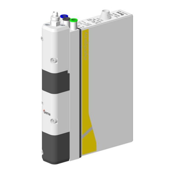
- Page 1 Rev. 03 1011 526 Operating instructions and Spare parts list Application pump OptiSpray AP01.1-E Translation of the original operating instructions...
- Page 2 To the best of our knowledge and belief, the information contained in this publication was correct and valid on the date of publication. Gema Switzerland GmbH makes no representations or warranties with respect to the contents or use of this publication, and reserves the right to revise this publication and make changes to its content without prior notice.
-
Page 3: Table Of Contents
Maintenance interval monitoring .............. 19 Assembly / Connection Assembly guide ..................... 21 Connection instructions ..................22 Start-up Preparation for start-up ..................25 Basic conditions ..................25 Basic information ..................25 Operation Operation ......................27 Table of contents 3 OptiSpray AP01.1-E... - Page 4 Spare parts list Ordering spare parts ..................... 49 OptiSpray AP01.1-E Application pump ..............50 OptiSpray AP01.1-E – spare parts ............... 51 OptiSpray Twin AP01.1-E Application pump ............52 OptiSpray Twin AP01.1-E – spare parts .............. 53 Connecting material ....................54 Diffuser (OptiGun GA03-E) ...................
- Page 5 Rev. 03 01/21 Table of contents 5 OptiSpray AP01.1-E...
-
Page 7: About These Instructions
General information This operating manual contains all important information which you require for the working with the OptiSpray AP01.1-E. It will safely guide you through the start-up process and give you references and tips for the optimal use when working with your powder coating system. -
Page 8: Structure Of Safety Notes
Presentation of the contents Figure references in the text Figure references are used as cross references in the descriptive text. Example: "The high voltage (H) created in the gun cascade is guided through the center electrode." 8 About these instructions OptiSpray AP01.1-E... -
Page 9: Safety
If this product is to be used for other purposes or other substances outside of our guidelines then Gema Switzerland GmbH should be consulted. -
Page 10: Product Specific Security Regulations
– It must be ensured, that all components are earthed according to the local regulations before start-up. For further security information, see the more detailed Gema safety regulations! WARNING Working without instructions Working without instructions or with individual pages from the instructions may result in damage to property and personal injury if relevant safety information is not observed. -
Page 11: Product Description
CG12-CP (automatic equipment) or the OptiStar CG11-P Control unit (manual equipment). The application pump will only operate in combination with the OptiGun GA03-E automatic gun or with other Gema models with a suitable diffuser (spraying air adapter). Please contact Gema if you have any further queries. -
Page 12: Reasonably Foreseeable Misuse
Compressed air connection - 8 mm Inlet pressure 6 bar ≈ 2.0 Nm³/h Max. compressed air consumption Max. water vapor content of the 1.3 g/m³ compressed air Max. oil vapor content of the compressed 0.1 mg/m³ 12 Product description OptiSpray AP01.1-E... -
Page 13: Powder Output (Reference Values)
The specified value is applicable only for this product itself and does not take into account external noise sources or cleaning impulses. The sound pressure level may vary, depending on the product configuration and space constraints. Product description 13 OptiSpray AP01.1-E... -
Page 14: Rating Plate
Rev. 03 01/21 Rating plate fig. 2 14 Product description OptiSpray AP01.1-E... -
Page 15: Design And Function
Inside diameter 4.5 mm In OptiCenter Inside diameter 7 OptiCenter suction OC03/OC05 tube/hose max. 30 cm In manual Inside diameter 4.5 mm, Inside diameter 7 equipment hose length max. 1.5 m OptiFlex 2 Spray Product description 15 OptiSpray AP01.1-E... -
Page 16: Spraying Air Function / Diffusers
Spraying air The OptiGun GA02 automatic gun and the OptiSelect GM03 manual gun must also be equipped with an appropriate diffuser adapter. The diffuser is grounded through the powder transport hose with conductive strips! 16 Product description OptiSpray AP01.1-E... -
Page 17: Connections
Transport air (Conveying Air IN) connection Pinch valve air connection External signal connection Pin assignment Connection 2.5 Ext., 12-pins Control signal +24 VDC Body – grounding PE Scope of delivery – Mains cable – Operating manual Product description 17 OptiSpray AP01.1-E... -
Page 18: Typical Properties - Characteristics Of The Functions
Powder chamber emptying combined with hose cleaning in both directions – Cleaning the hose to the gun only – Cleaning the hose on the suction side only (For details, see the operating instructions of the corresponding gun control unit) 18 Product description OptiSpray AP01.1-E... -
Page 19: Maintenance Interval Monitoring
OptiSpeeder! The pump is to be cleaned as a component of the entire system. Maintenance interval monitoring This function is provided by the OptiStar CG12-CP or the CG11-P Control unit. Product description 19 OptiSpray AP01.1-E... - Page 20 Rev. 03 01/21 20 Product description OptiSpray AP01.1-E...
-
Page 21: Assembly / Connection
Install the Application pump only in locations with an ambient temperature of between +15 and +40 °C, i.e. never next to heat sources (such as an enameling furnace) or electromagnetic sources (such as a control cabinet). Assembly / Connection 21 OptiSpray AP01.1-E... -
Page 22: Connection Instructions
8.1 Application pump no. 2 Gun cable Gun control Pinch valve air 10 Compressed air hose 11 Hose coupling Ø 8/6 – Ø Spraying air hose 6/4 mm Transport air hose 12 Powder hopper Control signal cable 22 Assembly / Connection OptiSpray AP01.1-E... - Page 23 – Check ground connections with Ohm meter and ensure 1 MOhm or less. The compressed air must be free of oil and water! Close the unused connections with the provided dust protection caps! Assembly / Connection 23 OptiSpray AP01.1-E...
- Page 24 Rev. 03 01/21 24 Assembly / Connection OptiSpray AP01.1-E...
-
Page 25: Start-Up
– At the suction area, a homogeneous fluidization must be ensured, so that no air ducts (craters) can be formed Start-up 25 OptiSpray AP01.1-E... - Page 26 Rev. 03 01/21 26 Start-up OptiSpray AP01.1-E...
-
Page 27: Operation
For a better understanding of the interrelationships in powder coating, it is recommended to read completely the operating instructions of the control unit and the powder gun, so as to be familiar with their functions too. Operation 27 OptiSpray AP01.1-E... - Page 28 Rev. 03 01/21 28 Operation OptiSpray AP01.1-E...
-
Page 29: Maintenance / Repairs
The parts to be replaced during maintenance work are available as spare parts. For further information, see chapter "Spare parts list". General information The product is designed to require a minimum of maintenance. Maintenance / Repairs 29 OptiSpray AP01.1-E... -
Page 30: Maintenance Of The Dense Phase Pump
– see below. Wearing parts The wearing parts to be replaced during the OptiSpray AP01 Application pump maintenance are available separately (see spare parts list). 30 Maintenance / Repairs OptiSpray AP01.1-E... -
Page 31: Cleaning
Periodic checks The periodic checks include examining all connecting cables and hoses. The corresponding parts should be replaced immediately if any damage to cables or hoses is discovered. All plugs must be properly tightened. Maintenance / Repairs 31 OptiSpray AP01.1-E... -
Page 32: Repair Work
Repair work In the event of malfunctions or faults, the product must be checked and repaired by an authorized Gema service workshop. The repairs must only be performed by an authorized specialist. Improper tampering can result in serious danger for user and equipment. -
Page 33: Pump Disassembly
Rev. 03 01/21 Required Tools fig. 9 Dismantling tool Allen key size 4 mm (Order number: 1012 909) Allen key size 3 mm Open-ended wrench 16 mm Pump disassembly Maintenance / Repairs 33 OptiSpray AP01.1-E... -
Page 34: Replacing The Pinch Valve Hoses
► Make sure that the positioning tabs are set correctly! ATTENTION Broken pinch valve hose may cause the clogging of the fluid blocking plate ► Clean or replace the corresponding fluid blocking plate! 34 Maintenance / Repairs OptiSpray AP01.1-E... -
Page 35: Replacing The Filter Elements
Operate the Application pump with powder at least 1/2 hour after replacing the filter elements. ► After the running-in of the filter elements a stable powder output value will be reached. Maintenance / Repairs 35 OptiSpray AP01.1-E... -
Page 36: Replacing The Solenoid Valves For Pinch Valves Control
Hexagon screwdriver 3 mm Phillips screwdriver PH0 Hexagon screwdriver Hexagon screwdriver 2.5 mm 4 mm Required spare parts AP01 Solenoid valve Gema order no. Suction pinch valve 1009 936 Conveying pinch valve 1009 936 36 Maintenance / Repairs OptiSpray AP01.1-E... -
Page 37: Replacing The Solenoid Valves
Rev. 03 01/21 Replacing the solenoid valves Maintenance / Repairs 37 OptiSpray AP01.1-E... - Page 38 Rev. 03 01/21 38 Maintenance / Repairs OptiSpray AP01.1-E...
- Page 39 Rev. 03 01/21 The assembly takes place in reverse order! Maintenance / Repairs 39 OptiSpray AP01.1-E...
-
Page 40: Replacing The Application Pump In An Opticenter
Replacing the Application pump in an OptiCenter Remove the powder from the system Start the cleaning program, rinse in both directions Depressurize/vent OptiCenter Next steps are described in the corresponding OptiCenters operating manual 40 Maintenance / Repairs OptiSpray AP01.1-E... -
Page 41: Fault Clearance
Powder hoses tend to clogging Clean or replace the powder hoses due to sintering Oil or water in the system Ensure that oil or water will be separated before entering into the Application pump Fault clearance 41 OptiSpray AP01.1-E... - Page 42 Rev. 03 01/21 Incident Causes Corrective action Transport air offset C3 not Adapt transport air offset C3 (see adapted to powder output operating manual OptiStar CG12- CP or CG11-P, section "Correction values") 42 Fault clearance OptiSpray AP01.1-E...
- Page 43 Start the pinch valve diagnostic Diagnosis OK? Use a replacement pump Start the pinch valve diagnostic Send in the defective Diagnosis OK? pump for repair Failure in the control unit or outside of the pump Fault clearance 43 OptiSpray AP01.1-E...
- Page 44 Rev. 03 01/21 44 Fault clearance OptiSpray AP01.1-E...
-
Page 45: Decommissioning / Storage
If the physical conditions are maintained, the unit can be stored indefinitely. Space requirements The space requirements correspond to the size of the product. There are no special requirements concerning distance to neighboring equipment. Decommissioning / Storage 45 OptiSpray AP01.1-E... -
Page 46: Physical Requirements
Storage must be inside a dry building at a temperature between +5 and +50 °C. Do not expose to direct sunlight! Maintenance during storage Maintenance schedule No maintenance schedule is necessary. Maintenance works During long-term storage, periodically perform a visual check. 46 Decommissioning / Storage OptiSpray AP01.1-E... -
Page 47: Disposal
Requirements on personnel carrying out the work The disposal of the product is to be carried out by the owner or operator. When disposing of components that are not manufactured by Gema, the instructions in the respective manufacturer’s documentation must be observed. - Page 48 Rev. 03 01/21 48 Disposal OptiSpray AP01.1-E...
-
Page 49: Spare Parts List
When using the spare parts from other manufacturers the explosion protection is no longer guaranteed. If any damage is caused by this use all guarantee claims become invalid! ► Only original Gema spare parts should be used! Spare parts list 49 OptiSpray AP01.1-E... -
Page 50: Optispray Ap01.1-E Application Pump
Rev. 03 01/21 OptiSpray AP01.1-E Application pump OptiSpray AP01.1-E Application pump – complete (pos. 1-14, 26-27) 1015 448 Allen cylinder screw – M5x130 mm 1010 431 Upper end piece 1010 428 Filter element – 3 µm, complete 1013 287# Filter element bushing... -
Page 51: Optispray Ap01.1-E - Spare Parts
Rev. 03 01/21 OptiSpray AP01.1-E – spare parts fig. 11 Item Tightening torque [Nm] 4.4 (greased) 3.1 (greased) 4.4 (greased) Spare parts list 51 OptiSpray AP01.1-E... -
Page 52: Optispray Twin Ap01.1-E Application Pump
Nut with kink protection – M12x1-Ø 8 mm 201 316 Maintenance set – pos. 3.2 (2x), 6 (2x), 6.1 (1x), 11 (2x), 12 (4x), 19 (1x), 27 (1x) 1015 436 * Please indicate length # Wearing part 52 Spare parts list OptiSpray AP01.1-E... -
Page 53: Optispray Twin Ap01.1-E - Spare Parts
Rev. 03 01/21 OptiSpray Twin AP01.1-E – spare parts fig. 12 Item Tightening torque [Nm] 4.4 (greased) 3.1 (greased) 4.4 (greased) Spare parts list 53 OptiSpray AP01.1-E... -
Page 54: Connecting Material
Connecting cable – 12 pins, 10 m 1000 976 Connecting cable – 12 pins, 15 m 1000 977 Connecting cable – 12 pins, 20 m 1000 978 * Please indicate length fig. 13: Connecting material 54 Spare parts list OptiSpray AP01.1-E... -
Page 55: Diffuser (Optigun Ga03-E)
Adaptor piece – complete, incl. pos. 6 1011 625 Hose connection – complete, incl. pos. 9 1011 632 O-ring – Ø 9x1.5 mm 1011 637 * Please indicate length #Wearing part fig. 14: Diffuser (OptiGun GA03-E) Spare parts list 55 OptiSpray AP01.1-E... -
Page 56: Diffuser (Optiselect Pro Gm04-E)
Adaptor piece – complete, incl. pos. 6 and 7 1019 533 Hose connection – complete, incl. pos. 10 1011 632 O-ring – Ø 9x1.5 mm 1011 637 * Please indicate length # Wearing part fig. 15: Diffuser (OptiSelect Pro GM04-E) 56 Spare parts list OptiSpray AP01.1-E... -
Page 57: Diffuser (Optiselect Gm03-E)
Adaptor piece – complete, incl. pos. 6 and 7 1011 626 Hose connection – complete, incl. pos. 10 1011 632 O-ring – Ø 9x1.5 mm 1011 637 * Please indicate length # Wearing part fig. 16: Diffuser (OptiSelect GM03-E) Spare parts list 57 OptiSpray AP01.1-E... - Page 59 Sound pressure level ........13 Spare parts list ..........49 Main functions ..........18 Spraying air function / diffusers ....... 16 Maintenance ............. 29 Start-up ............25 Maintenance during storage ......46 Storage ............45 Spare parts list 59 OptiSpray AP01.1-E...
- Page 60 Rev. 03 01/21 Storage conditions ........... 45 Switching on and off Technical Data ..........12 Conveying procedure ........27 Typical characteristics ........18 Rinsing procedure ........27 Wearing parts ........... 30 60 Index OptiSpray AP01.1-E...
- Page 62 Rev. 03...
Need help?
Do you have a question about the OptiSpray AP01.1-E and is the answer not in the manual?
Questions and answers