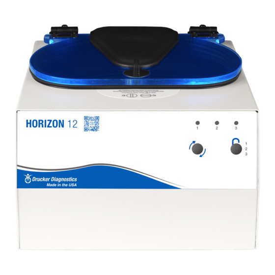
Summary of Contents for Drucker Diagnostics Horizon 12
- Page 1 200 Shadylane Drive Philipsburg, PA 16866 www.druckerdiagnostics.com Service Manual Horizon 12 Centrifuge DRUCKER DIAGNOSTICS SM015 HORIZON 12 SERVICE MANUAL REV A...
-
Page 2: Table Of Contents
Contents PREFACE INTENDED USE GENERAL DESCRIPTION OF MAJOR COMPONENTS WARRANTY INFORMATION SPECIFICATIONS TROUBLESHOOTING SERVICE INSTRUCTIONS WIRING DIAGRAM SPARE PARTS LIST DRUCKER DIAGNOSTICS SM015 HORIZON 12 SERVICE MANUAL REV A... -
Page 3: Preface
Failure to follow the procedures in this document may result in personal injury or instrument damage. Drucker Diagnostics will not be held liable for any injury or damage because of improper servicing. -
Page 4: Specifications
BALANCE ERROR Debris lodged within the Carefully inspect all rotor pockets, tube holders and crevasses for debris. 1 ERROR BUZZ + 2 REPEATING BEEPS rotor or tube carriers Rotor damaged Replacement required DRUCKER DIAGNOSTICS SM015 HORIZON 12 SERVICE MANUAL REV A... -
Page 5: Service Instructions
• Important: When verifying rotor speed, make certain that all carriers are installed in the rotor. • No calibration adjustment of speed can be made, only a verification of rotor speed. DRUCKER DIAGNOSTICS SM015 HORIZON 12 SERVICE MANUAL REV A... - Page 6 ‘ON’ state. Tighten each nut a ¼ turn in succession, trying each corresponding button as you go. • Once each control panel button clicks when pressed, installation is complete. DRUCKER DIAGNOSTICS SM015 HORIZON 12 SERVICE MANUAL REV A...
- Page 7 Attach the motor to the motor mount plate with four #8 screws and torque to 18 in-lbs (Fig 2). • Secure the motor wire harness with a zip tie as shown. Snip the tag end of the zip tie flush when complete. DRUCKER DIAGNOSTICS SM015 HORIZON 12 SERVICE MANUAL REV A...
- Page 8 (fig 7). • Install one fender washer onto each stud (fig 8). • Finish the assembly with one Nylok nut on each stud, and tighten to 13 in-lbs DRUCKER DIAGNOSTICS SM015 HORIZON 12 SERVICE MANUAL REV A...
- Page 9 • Secure the base with six #8 screws torqued to 10 in-lbs. (fig 11). • Install the exhaust cover and secure with three #8 screws torqued to 10 in-lbs. (fig 12). DRUCKER DIAGNOSTICS SM015 HORIZON 12 SERVICE MANUAL REV A...
- Page 10 Carefully place the cabinet onto the base taking care not to pinch any wires between the two. • Complete the assembly by replacing the eight #8 screws, with a 3/32 hex key. DRUCKER DIAGNOSTICS SM015 HORIZON 12 SERVICE MANUAL REV A...
- Page 11 8. WIRING DIAGRAM DRUCKER DIAGNOSTICS SM015 HORIZON 12 SERVICE MANUAL REV A...
- Page 12 9. SPARE PARTS LIST DRUCKER DIAGNOSTICS SM015 HORIZON 12 SERVICE MANUAL REV A...


Need help?
Do you have a question about the Horizon 12 and is the answer not in the manual?
Questions and answers