Table of Contents

Related Manuals for Fanimation Punkah FP720 Series


Summary of Contents for Fanimation Punkah FP720 Series
- Page 1 The Punkah ® Motor and Fan Unit Motor Assembly FP780_ _ Net Weight 17 lbs (7.71 kg) Fan Unit FP720_ _ Net Weight 7 lbs (3.18 kg) WARNING: Support Directly From Building Structure OWNER’S MANUAL READ AND SAVE THESE INSTRUCTIONS...
-
Page 2: Table Of Contents
Fanimation. 7. Fanimation reserves the right to modify or discontinue any product at any time and may substitute any part under this warranty. 8. Under no circumstances may a fan be returned without prior authorization from Fanimation. The receipt of purchase must accompany authorized returns and must be sent freight prepaid to Fanimation. -
Page 3: Tools Needed For Assembly
Fanimation. Substitution of parts or accessories not designated for use with this product by Fanimation could result in personal injury or property damage. Contact your retail store for missing or damaged parts. -
Page 4: Electrical And Structural Requirements
Electrical and Structural Requirements Your new fan will require a grounded electrical supply line of 120 volts AC, 60 Hz, 15 amp circuit. The outlet box must be securely anchored and capable of withstanding a load of at least 100 lbs. Figure 1 depicts different structural confi... -
Page 5: Hanging Options
Please choose one of two hanger options for your fan: NOTE: Both The Motor Base And The Fan Head Base MUST Be Mounted On The Same Surface (Plane). Option 1 - Ceiling Mount (Figure 2a) Option 2 - Wall Mount (Figure 2b) INSTALLATION NOTE Fan Motor can be mounted at either end of fi... -
Page 6: Motor Mounting Bracket Hanging Options - Ceiling Or Wall Mount
Motor Mounting Bracket Hanging Options - Ceiling or Wall Mount INSTALLATION NOTE The following illustrations serve as a guide on mounting and securing your motor assembly either to the ceiling or to the wall. Building structure designs will vary depending on the local building codes. Be sure of your layout plans before fastening your motor assembly unit. -
Page 7: Wiring Your Motor Assembly - Ceiling Or Wall Mount
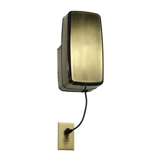
Power Options for Your Motor Assembly - Ceiling or Wall Mount ▲WARNING To avoid possible electrical shock, be sure electricity is turned off at the main fuse box before wiring. Option 1 - Direct Plug-In Socket: 1. Position mounting plate with the outlet nearby. Attach mounting plate to ceiling or wall with a minimum of two lag bolts into building structure (see previous page). -
Page 8: Mounting Head Assembly
INSTALLATION NOTE The following illustrations serve as a guide on mounting and securing your motor assembly either to the ceiling or to the wall. Building structure designs will vary depending on the local building codes. Be sure of your layout plans before fastening your fan head unit. ▲WARNING To reduce risk of personal injury, do NOT mount the fan unit into (dry) wall or ceiling board only. -
Page 9: Assembling & Adjusting Connecting Rod Length
Assembling & Adjusting Connecting Rod Length 1. Loosen each of the “outer” set screws on the outer rod assembly. 2. Insert each “inner” rod assembly (2 pcs) equal amounts so that the distance between connecting rod end holes is equal to the distance between the center of the motor shaft and center of the blade holder or same as the distance between blade holder to blade holder. - Page 10 Attaching Connecting Rods (cont’d) Option 1 - Single Linkage Confi guration (Figure 15a) Option 2 - Double Linkage Confi guration (Figure 15b) Blade Holder End 1. Place screw through connecting rod end, nylon washer, and blade holder to match your application. 2.
-
Page 11: Installing The Blades
▲WARNING To reduce the risk of personal injury, do not bend the blade holders when installing, balancing the blades or cleaning the fan. NOTE: Blade(s) are not included and sold seperately. Assembling the Fan Blades 1. Position the palm leaf, or the woven bamboo, or the wicker blade over the blade holder with the threaded posts showing. -
Page 12: Parts List
Contact your retail store for repair parts. Part # FP780** C7821** C7823 C7800 ˝-32 x ˝ (3) HDWMP780 ˝-18 x 2¼˝ ˝-18 x 1¾˝ HDWRM780 C7805 Part # FP720** C7225** C7224** ˝-24 x ˝ (2) HDW720 ˝-18 x 2˝ ˝-18 x 1½˝... -
Page 13: Exploded-View Drawing
The Punkah ® Parts Illustration NOTE: The illustration shown is not to scale or its actual confi guration may vary. Wires partially removed for clarity. Figure 18... -
Page 14: Trouble Shooting
For your own safety turn off power at fuse box or circuit breaker before trouble shooting your fan. Trouble 1. FAN WILL NOT START 1. Fuse or circuit breaker blown. 2. Loose power line connections to the fan, or loose wire connections in the control housing. - Page 16 10983 Bennett Parkway Zionsville, IN 46077 Toll Free (888) 567-2055 FAX (866) 482-5215 Outside U.S. call (317) 733-4113 Visit Our Website www.fanimation.com Copyright 2008 Fanimation 2008/04...