Table of Contents

Related Manuals for Fanimation Evanesce FP2700 Series


Summary of Contents for Fanimation Evanesce FP2700 Series
-
Page 1: Ceiling Fan
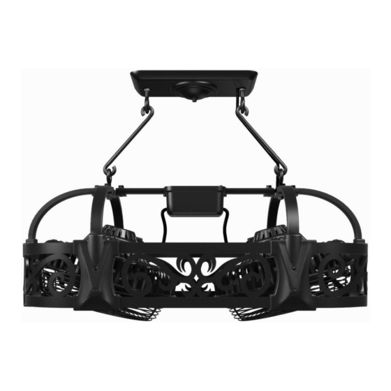
The Evanesce ® Ceiling Fan Suitable for use with Solid State Speed Controls WARNING: Support Directly From Building Structure Net Weight 75 lbs (33.5 kg) Model No. FP2700 Series OWNER’S MANUAL READ AND SAVE THESE INSTRUCTIONS... -
Page 2: Table Of Contents
Fanimation. 7. Fanimation reserves the right to modify or discontinue any product at any time and may substitute any part under this warranty. 8. Under no circumstances may a fan be returned without prior authorization from Fanimation. The receipt of purchase must ac- company authorized returns and must be sent freight prepaid to Fanimation. -
Page 3: Unpacking Instructions
Fanimation. Substitution of parts or accessories not designated for use with this product by Fanimation could result in personal injury or property damage. Contact your retail store for missing or damaged parts. -
Page 4: Electrical And Structural Requirements
Electrical and Structural Requirements Your new ceiling fan will require a grounded electrical supply line of 120 volts AC, 60 Hz, 15 amp circuit. The outlet box must be securely anchored and capable of withstanding a load of at least 100 lbs. Figure 1 depicts different structural configurations that may be used for mounting the outlet box. -
Page 5: How To Set And Operate Your C24 Hand-Held Remote
How to Set and Operate Your C24 Hand-held Remote If you feel that you do not have enough electrical wiring knowledge or experience, have your fan installed by a licensed electrician. ▲WARNING To avoid possible electrical shock, be sure electricity is turned off at the main fuse box before wiring. -
Page 6: How To Set And Operate Your C25 Wireless Wall Control
How to Set and Operate Your C25 Wireless Wall Control If you feel that you do not have enough electrical wir- ing knowledge or experience, have your fan installed by a licensed electrician. ▲WARNING To avoid possible electrical shock, be sure electricity is turned off at the main fuse box before wiring. -
Page 7: Hanger Options
Please choose one of two hanger options for your ceiling fan: Option 1 - Hanger Canopy Mount (Figure 8a) 1. Place the Hanger Canopy Assembly on the ceiling covering the junction box. 2. Attach the assembly to the ceiling using two 5˝ Lag Bolts. Choose any 2 opposing holes in the canopy assembly which will allow the Lag Bolts to screw in into the wood structure of the building. -
Page 8: Wiring Your Ceiling Fan - Hanger Canopy Mount
Wiring Your Ceiling Fan - Hanger Canopy Mount ▲WARNING To avoid possible electrical shock, be sure electricity is turned off at the main fuse box before wiring. Figures 10 & 10a 1. Position the wire up the chain or hanger rod. Attach the wire with supplied wire ties. -
Page 9: Wiring Your Ceiling Fan - Hanger Eye Bolt Mount
Wiring Your Ceiling Fan - Hanger Eye Bolt Mount ▲WARNING To avoid possible electrical shock, be sure electricity is turned off at the main fuse box before wiring. Figures 11 & 11a 1. Attach the sheet metal strap to the ceiling junction box with the screws provided with the junction box. -
Page 10: How To Install Your Light Kit - Lk27 (Optional)
How to Install Your Light Kit - LK27 (Optional) ▲WARNING To avoid possible electrical shock, be sure electricity is turned off at the main fuse box before wiring. 1. Turn off power. 2. Remove Rubber Plug from screw hole. 3. Remove the “plain” side covers with the Philips screwdriver. -
Page 11: How To Change Your Light Bulbs
How to Change Your Light Bulbs ▲WARNING To prevent over-heating or electrical fi res, use ONLY 120 volt, 40 or 60 watt, incadescant bulbs as specifi ed. 1. Turn off power. 2. Remove the faulty bulb(s). By gently, twisting counter- clockwise and pulling out the bulb (Figure 14). -
Page 12: Parts List
Parts List Model #FP2700 Ref. # Description Fan Motor Assembly Canopy Assembly Control Receiver Unit (inside Control Housing) Canopy Ceiling Assembly Side Cover Light Kit † Wire Nut Wire Tie Flat Washer 5˝ Lag Bolt 80˝ Hanging Chain 4˝ Lag Eye Bolt “S”... -
Page 13: Exploded-View Drawing
The Evansece NOTE: The illustration shown is not to scale or its actual confi guration may vary. Wires partially removed for clarity. FP2700 ® Parts Illustration Figure 15 Optional - Sold Separately LIGHT FAN OFF... -
Page 14: Trouble Shooting
For your own safety turn off power at fuse box or circuit breaker before trouble shooting your fan. Trouble 1. FAN WILL NOT START 1. Fuse or circuit breaker blown. 2. Loose power line connections to the fan, or loose switch wire connections in the switch housing. - Page 16 10983 Bennett Parkway Zionsville, IN 46077 (888) 567-2055 FAX (866) 482-5215 Outside U.S. call (317) 733-4113 Visit Our Website @ www.fanimation.com Copyright 2006 Fanimation 2006/02...