Fanimation Brewmaster FP10 Series Owner's Manual
Belt-driven ceiling fans
Hide thumbs
Also See for Brewmaster FP10 Series:
- Specification sheet (2 pages) ,
- Owner's manual (16 pages) ,
- Owner's manual (36 pages)
Table of Contents
Advertisement
Quick Links
Download this manual
See also:
Owner's Manual
The Brewmaster
®
Belt-Driven Ceiling Fans
Long Neck FP20
Net Weight 15 lbs
(6.8 kg)
Motor Assembly
Net Weight 15 lbs
(6.8 kg)
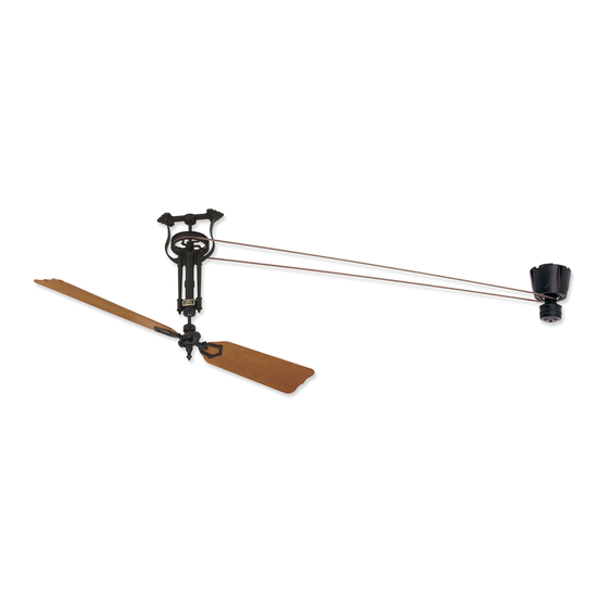
Short Neck FP10
Net Weight 11 lbs
(5.0 kg)
Suitable for use with Solid State Speed Controls
WARNING: Support Directly From Building Structure
Model No. FP10 / 20 Fan Series
Model No. FP1280 Motor Series
OWNER'S MANUAL
READ AND SAVE THESE INSTRUCTIONS
Advertisement
Table of Contents

Related Manuals for Fanimation Brewmaster FP10 Series


Summary of Contents for Fanimation Brewmaster FP10 Series
- Page 1 Short Neck FP10 Net Weight 11 lbs (5.0 kg) Suitable for use with Solid State Speed Controls WARNING: Support Directly From Building Structure Model No. FP10 / 20 Fan Series Model No. FP1280 Motor Series OWNER’S MANUAL READ AND SAVE THESE INSTRUCTIONS...
-
Page 2: Table Of Contents
Fanimation. 7. Fanimation reserves the right to modify or discontinue any product at any time and may substitute any part under this warranty. 8. Under no circumstances may a fan be returned without prior authorization from Fanimation. The receipt of purchase must ac- company authorized returns and must be sent freight prepaid to Fanimation. -
Page 3: (Motor Assembly) Unpacking Instructions And Parts Identifi Cation
Fanimation. Substitution of parts or accessories not designated for use with this product by Fanimation could result in personal injury or property damage. Contact your retail store for missing or damaged parts. -
Page 4: (Pulley Assembly) Unpacking Instructions And Parts Identifi Cation
Unpacking Instructions and Parts Identifi cation (cont’d) FP10 (Short)/FP20 (Long) Pulley Assembly and Hardware Parts Identifi cation FP10 Short Neck Pulley Assembly Blade Holder to Hub Screws 10-32 x ½˝ (5) Lag Bolts (4) & Flat Washers (4) Traditional Blade Screws, ˝-24 x... -
Page 5: Electrical And Structural Requirements
Electrical and Structural Requirements Your new ceiling fan will require a grounded electrical supply line of 120 volts AC, 60 Hz, 15 amp circuit. INSTALLATION NOTE It is recommended that each fan and the motor have ¾˝ plywood backing secured to a structural member for adequate support (Figure 3). -
Page 6: How To Set Your Remote Receiver
How to Set Your Switch Cap Remote Receiver This step is to be completed prior to hanging your motor. 1. Removing the Switch Housing: Remove the switch housing from the motor by unscrewing the three screws and unplugging the connector (Figures 1 & 2). 2. -
Page 7: How To Set And Operate Your C20 Remote Control
How to Set and Operate Your C20 Remote Control Must operate in conjunction with Switch Cap Control Receiver Be sure the electricity to the fan motor is turned off! 1. Setting the Code: The remote unit has 16 different code combinations. It may be necessary to test a couple frequency code settings to improve signal reception and/or eliminate interference from other remote control household items. -
Page 8: How To Hang And Wire Your Ceiling Fan
Fanimation. Substitution of parts or accessories not designated for use with this product by Fanimation could result in personal injury or property damage. Contact your retail store for missing or damaged parts. - Page 9 How to Hang and Wire Your Ceiling Fan (cont’d) If you feel that you do not have enough electrical wiring knowledge or experience, have your fan installed by a licensed electrician. ▲WARNING To avoid possible electrical shock, be sure electricity is turned off at the main fuse box before wiring.
-
Page 10: Belt Splicing Instructions
1. Wrap the belting around the two pulleys that will be connected and overlap the belting as shown. Use the spring clamps provided to hold the belting in place temporarily. With the clamps remaining in the same place, grasp both ends of the belting and pull tight. The clamps should hold the belting together after releasing the belt. -
Page 11: Mounting The Fan Blades
CAUTION Do not connect fan blades until the fan is completely installed. Hanging fan with blades connected may result in damage to the fan blades. Natural Palm Leaf, Woven Bamboo, Woven Wicker Blades 1. Lay side “A” of the blade holder on a fl at surface with the inside of the blade holder facing up. -
Page 12: Trouble Shooting
For your own safety turn off power at fuse box or circuit breaker before trouble shooting your fan. Trouble 1. FAN WILL NOT START 1. Fuse or circuit breaker blown. 2. Loose power line connections to the fan, or loose switch wire connections in the switch housing. -
Page 13: Exploded-View Drawing & Parts List, Motor Assembly
The Brewmaster Exploded-View Parts List Ref. # Description Brewmaster Motor Assembly Switch Cap Assembly Control Receiver Flat Washer Switch Cap Base Motor Pulley Motor Housing M/S, Washer Hd, -24 x 3½˝, Black Motor Hex Nut, -24 x 4mm (4) Lock Nut, Nylon Insert, -24 x 5mm (4) Canopy Assembly Belt Rivet Parts Bag Containing:... -
Page 14: Parts List, Pulley Assembly
How to Order Parts When ordering repair parts, always give the following information: • Part Number • Part Description • Fan Model Number Contact your retail store for repair parts. FP10 /FP20 P1212 HDWFP10HB HDWFP10LG ˝-24 x ½˝,Black (7), HDWFP10WB ˝-24 x ˝,Black (5) -
Page 15: Exploded-View Drawing, Pulley Assembly
The Brewmaster FP10__ / FP20__ (Short) Exploded-View NOTE: The illustration shown is not to scale or its actual confi guration may vary. Pulley Assembly Pack ® (Long) Figure 2... - Page 16 10983 Bennett Parkway Zionsville, IN 46077 Toll Free (888) 567-2055 FAX (866) 482-5215 Outside U.S. call (317) 733-4113 Visit Our Website www.fanimation.com Copyright 2008 Fanimation 2008/02...