
Subscribe to Our Youtube Channel
Related Manuals for Lumag RPi11N


Summary of Contents for Lumag RPi11N
- Page 1 Distribution Limited Compactor Wacker Plate Operator’s Manual RPi11N FOR YOUR SAFETY READ AND UNDERSTAND THE ENTIRE MANUAL BEFORE OPERATING THIS MACHINE...
- Page 3 For the warranty to be valid the Warranty Registration Form must be completed and returned to Lumag Distribution Limited within 14 days of the purchase, together with a copy of the purchase invoice. We will use your email to confirm that we have received the completed Warranty Registration Form and contact you about any errors or omissions on the form.
- Page 5 Lubricate X (2) Parts & Cables 1 – First service only, 2 = Should be carried out by your Lumag Dealer, 3 = May need to be done more often in dusty areas & 4 = Replace paper element only...
-
Page 7: Table Of Contents
CONTENTS Introduction…………………………………………………………………………………………… 2 Applications…………………………………………………………………………………………… 2 Structure…………………………………………………………………………………………………3 Functions and controls………………………………………………………………………………… 3 Accessories………………………………………………………………………………………………3 For safety operation………………………………………………………………………………………3 Hazards and risks…………………………………………………………………………………………4 Operation…………………………………………………………………………………………………6 Careand preventive maintenance ………………………………………………………………………12 Service …………………………………………………………………………………………………12 Specifications ………………………………………………………………………………………… 12 Troubleshooting ……………………………………………………………………………………… 13 Replacement and parts list …………………………………………………………………………… 13 INTRODUCTION Thank you for your selection of our equipment. We have taken care in the design, manufacture and testing of this product. -
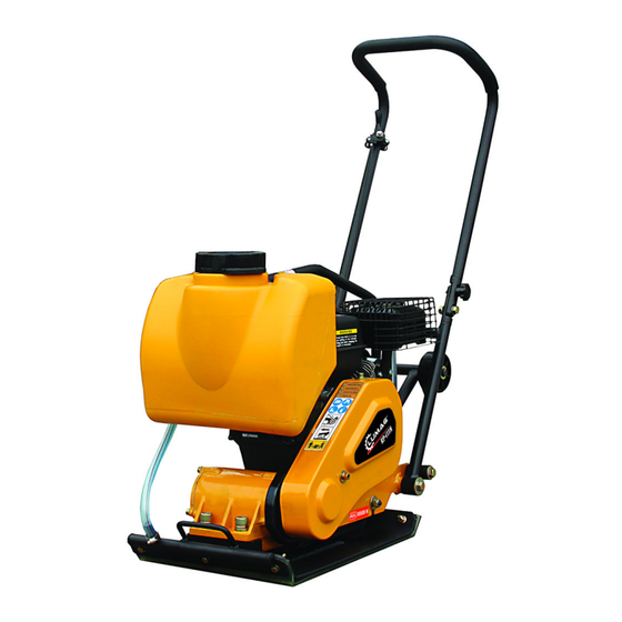
Page 8: Structure
rather effective.Please use this compactor for compacting surface on soil, sediment, sand , beaching and asphalt. It is not recommended for use this machine for the other applications. STRUCTURE The upper part is made up of Power Source, Handle ,Belt Cover and Guard Hook which are fixed by Engine base. -
Page 9: Hazards And Risks
respect and caution. Misuse or carelessness can result in serious injury or damage. or both. Safety precautions must be observed at all times. Operator Qualifications: Before operating this equipment, an individual should read this manual. Whenever possible, he should be shown how to operate the unit by an experienced operator. - Page 10 SERIOUS INJURY could result from improper or careless use of this machine Plate compactors are heavy units and should be positioned by two people of appropriate strength. Using the lifting handles provided on the machine, along with correct lifting techniques. ! MECHANICAL HAZARDS DO NOT operate the machine unless all protective guards are in place.
-
Page 11: Operation
DO NOT over fill the fuel tank and avoid spilling petrol when refueling. Spilled petrol or petrol vapour may ignite. If spillage occurs,ensure that the area is dry before starting the motor. ENSURE theat the fuel tank cap is securely fitted after refueling. ! CHEMICAL HAZARDS DO NOT operate or refuel a petrol or diesel motor in a confined area without adequate ventilation. - Page 12 Use unleaded grade petrol and ensure that the fuel is free from contamination. The vibratory motion provides a self propelling action. Position the handle at the opposite end of the machine to the vibrator. Start the motor using the recoil starter. ( If the motor is fitted with an on/off switch this must first be turned to ON before starting.
- Page 13 ! IMPORTION Use the motor oil SAE When changing the oil, the old oil can be drained by tipping the unit. The oil will drain easily while it is hot. 1-6. A regular grade gasoline should be used in the engine. When filling the fuel tank, make sure the fuel filter is used.
- Page 14 If the engine is cold or the ambient temperature is low, close the choke lever fully. Fig-6 3-5. Pull the starter handle slowly until resistance is felt. This is the “compression”point. Return the handle to its original position and pull swiftly. Do not pull out the rope all the way.
- Page 15 If the engine stops and will not restart, check the engine oil level. 4-3. When compacting asphalt, it is advisable to paint the bottom face of the vibrating plate with diesel fuel. This will assist in preventing the plate from sticking to the asphalt. 4-4.
- Page 16 A. AIR CLEANER SERVICE Fig-14 Dirty air cleaner element will cause starting difficulty, power loss, engine malfunctions, and shorten engine life extremely. Keep the air cleaner element clean. URETHANE FOAM ELEMENT Remove the element and wash it in kerosene or diesel fuel. Then saturate it in a mixture of 3 parts kerosene or diesel fuel and 1 part engine oil.
-
Page 17: Careand Preventive Maintenance
CARE AND PREVENTIVE MAINTENANCE Check the oil level in the motor crankcase daily. Check the vibrator oil level weekly. Inspect the rubber anti vibration mounts for wear or deterioration. Clean the underside of the plate regularly to prevent a build up of material. -
Page 18: Troubleshooting
TROUBLESHOOTING SYMPTOM POSSIBLE CAUSES AND CORRECTION Motor will not start -Check the ON/OFF switch to ensure that it is switched ‘ON’. -Check the fuel supply. -If a Honda or Kama motor is fitted check the crankcase oil level as and oil sensor device is fitted to these motors which prevents starting and stops the motor when the oil level is low. - Page 20 •Major components list PART NO. DESCRIPTION 100001 Engine 100002 the upper half of Handle(Optional ) 100003 locknut M10(Optional ) Washer ¢10(Optional ) 100004 100005 Washer ¢10(Optional ) 100006 Hexagonal bolt M10*35(Optional ) 100007 Offset ring bolt M10(Optional ) 100008 the lower half of Handle(Optional ) 100009 Rubber Spring washer ¢12...
- Page 21 •Water tank (Optional) parts list 100044 Socket head bolt M8*25(Optional) Washer ¢8(Optional) 100045 100046 Water tank cap(Optional) Washer ¢8(Optional) 100047 100048 Lock nut M8(Optional) 100049 Water tank(Optional) 100050 water pipe(Optional) 100051 Water valve(Optional) 100052 Hose band (Optional) 100053 Water pipe(Optional)
- Page 23 • Vibrator Assembly Parts List PART NO. DESCRIPTION 100026-01 paper cushion 100026-02 Case cover/pulley 100026-03 Washer M8 100026-04 Hexagonal bolt M8*25 100026-05 Cover seal, vib. 100026-06 Ecc. Rotary shaft 100026-07 Flat key 8*7*16 100026-08 Pulley, driven 100026-09 Washer ¢10 Spring washer ¢10 100026-10 100026-11 Hexagonal bolt M10*25...
- Page 24 Unit 10, Hatchmoor Industrial Estate, Hatherleigh, Okehampton, Devon EX20 3LP www.lumag-gb.co.uk 01837 811741 Lumag Distribution Limited Company Number: 09267547 VAT Number: GB154566788 Hatherleigh Plant and Tool Hire is a trading name of Lumag Distribution LTD...
Need help?
Do you have a question about the RPi11N and is the answer not in the manual?
Questions and answers