Table of Contents
Advertisement
Advertisement
Table of Contents

Related Manuals for Topcon SP-3000P


Summary of Contents for Topcon SP-3000P
- Page 1 INSTRUCTION MANUAL SPECULAR MICROSCOPE -3000P...
- Page 2 Before using this instrument, carefully read the "DISPLAY FOR SAFE USE" and the "SAFETY CAUTIONS" to familiarize yourself with the features of the SP-3000P Specu- lar Microscope and to ensure that you operate it efficiently and safely.
-
Page 3: Cautions For Use
The patient may be injured. To avoid electric shock, do not open the instrument. Request service from an authorized Topcon distributor. Electric shock may cause burns or a possible fire. Turn the power switch OFF and unplug the power cord before replacing the fuses. -
Page 4: Display For Safe Use
DISPLAY FOR SAFE USE To encourage safe and proper use and to prevent danger to the operator and others or potential damage to property, important cautionary messages are placed on the instrument body and inserted in the instruc- tion manual. We suggest that everyone using the instrument understands the meaning of the following displays, icons and text before reading the "SAFETY CAUTIONS"... -
Page 5: Safety Cautions
SAFETY CAUTIONS WARNING Icon Prevention item Page To avoid fire and electric shock in case of leakage, be sure to use a power supply equipped with a 3-plug AC receptacle for proper grounding. Electric shock may cause burns or a possible fire. Turn the power switch OFF and unplug the power cord before replacing the fuses. - Page 6 OFF and unplug the power cord before maintenance. To avoid electric shock, do not open the instrument. Request service from an ----- authorized Topcon distributor. This instrument has been tested (with 120V/230V) and found to comply with IEC60601-1-2: 2001. This instrument radiates radio frequency energy within standard and may affect other devices in the vicinity.
-
Page 7: Usage And Maintenance
P.74. ESCAPE CLAUSE • TOPCON shall not take any responsibility for damage due to fire, earthquakes, actions by third per- sons and other accidents, or damage due to negligence and misuse by the user and any use under unusual conditions. -
Page 8: Warning Displays And Positions
To ensure safety, the instrument provides warning displays. Use the instrument correctly by observing the display instructions. If any of the following display labels are missing, contact your dealer or TOPCON at the address on the back cover. CAUTION To avoid injury, be careful not to... -
Page 9: Table Of Contents
CONTENTS CAUTIONS FOR USE .......................... 2 ENVIRONMENTAL CONDITIONS FOR USE ..................2 STORAGE, USAGE PERIOD AND OTHERS ..................2 ENVIRONMENTAL CONDITIONS FOR PACKAGING IN TRANSPORTATION / STORAGE ..... 2 CHECKPOINTS FOR MAINTENANCE ....................2 DISPLAY FOR SAFE USE ........................3 SAFETY CAUTIONS .......................... - Page 10 MAINTENANCE AND INSPECTION .................... 69 MAINTAINING ACCURACY ....................... 69 MAINTENANCE AND INSPECTION ..................72 MAINTENANCE ..........................73 CLEANING THE DUST COVER, CONTROL PANEL, MONITOR SCREEN, ETC....73 CLEANING THE PARTS WHICH COME INTO CONTACT WITH THE PATIENT ....73 CLEANING THE PHOTOGRAPHY WINDOW ................
-
Page 11: Nomenclature
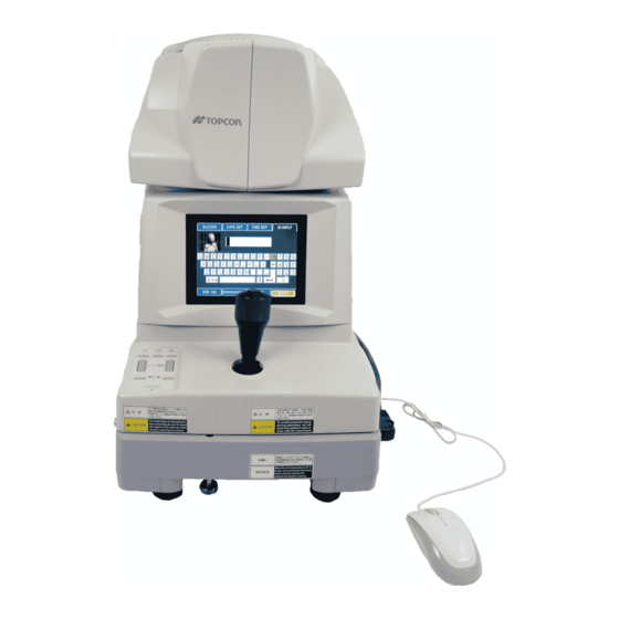
NOMENCLATURE MAIN COMPONENT NAMES Lamp house cover Photography head unit Color video monitor Photography switch Base unit Joystick Brightness volume Control panel Power lamp RS-232C input terminal Power supply unit VIDEO OUT output terminal USB output terminal Locking knob (for movement) Forehead rest Photography window Vertical positioning mark... -
Page 12: Control Panel
CONTROL PANEL Clear switch Delete switch Menu switch Image selector switch Image transfer switch Chinrest down switch Chinrest up switch Power LED Delete switch : Deletes the image being displayed. Menu switch : Displays the menu. Clear switch : Deletes all the images in the memory. Image transfer switch : Transfers the image data through USB. - Page 13 Corneal endothelium display 0001 Longitudinal alignment bar Image display Eye to be photographed [Photography point] Photography serial number Date R [ C ] 0001 05/08/05 13:38 0.540 Time Image of corneal 1000 Corneal thickness endothelium 1500 Cell chart 2000 DATA icon 2500 Used for output to the 3000...
- Page 14 Simplified cell count mode display L [ C ] 0037 Number of cells analyzed Magnified image of corneal endothelium EXIT Menu display Icon Notation of mouse operation This instruction manual is described according to the following notation rule. Notation Click: Press the left button on the mouse and release it at once. •...
-
Page 15: Standard Accessories
STANDARD ACCESSORIES Upon unpacking, make sure that all the following standard accessories are included. Figures in ( ) are the quantities. Power cord (1) Chinrest tissue pin (2) Mouse (1) Emergency chinrest knob (1) Chinrest tissue (2) Dust cover (1) Fuse (2) Instruction manual (1) NOMENCLATURE... -
Page 16: Preparatons Before Use
PREPARATONS BEFORE USE INSTALLING THE INSTRUMENT To avoid injury and/or damage to the instrument, hold the instrument in CAUTION the specified position and be careful not to shake or move it suddenly. When carrying the instrument, be careful not to drop or tip it over. Be CAUTION careful to prevent your hand from being pinched by the instrument. -
Page 17: Connecting The Power Cord
CONNECTING THE POWER CORD To avoid fire and electric shock in case of leakage, be sure to use a power sup- WARNING ply equipped with a 3-plug AC receptacle for proper grounding. CAUTION To avoid electric shock, do not handle the plugs with wet fingers. Make sure that the switch of the instrument is OFF ( POWER... -
Page 18: Connecting The External Input/Output Terminal
CONNECTING THE EXTERNAL INPUT/OUTPUT TERMINAL Image output This instrument can be connected to an image processing unit of the EIA (NTSC) signal method. Connect one end of the connection cord to the VIDEO OUT terminal on the instrument. Connect the other end to the image processing unit. The VIDEO OUT of the instrument has a BNC terminal. - Page 19 Connect the connection cord to the RS-232C input terminal on the instrument. Connect the other end to an external device, etc. RS-232C input terminal For assistance in connecting this instrument, contact your authorized Topcon distributor listed on the back cover. PREPARATONS BEFORE USE...
-
Page 20: Default Setting
DEFAULT SETTING In default setting, it is possible to set the DATA input/output, the power saving time and the video OUT output, and to check the operation. Preparation for "default setting" Make sure that the power cord is connected properly. Refer to "CONNECTING THE POWER CORD"... - Page 21 Transmission method RTS-CTS RTS-CTS control TOPCON NEW format Relation between the output format and transmission method When you want to set the transfer speed of data, fit the mouse pointer to the "2400" or "9600" icon of the "BAUD RATE" column and click it.
- Page 22 IMAGE "DATA OUT" dialog box When you want to add the image data output to the USB output format, fit the mouse pointer to the "ON" icon of the "IMAGE" column and click it. When you do not want to output the image data, fit the mouse pointer to the "OFF" icon of the "IMAGE"...
- Page 23 Setting the instrument number You can set the instrument number. "01" is set when shipped. Fit the mouse pointer to the "SP No." tab in the upper section and click it. The "SP No." dialog box appears. "SP No." tab Instrument number display area "Ten key"...
- Page 24 Setting the DATA input You can set the data input from the outside through the RS-232C input terminal. The set icon is outlined in yellow. "OFF" (No input) is set when shipped. Fit the mouse pointer to the "DATA IN" tab in the upper section and click it The "DATA IN"...
- Page 25 How to finish setting Move the mouse to fit the mouse pointer to the "EXIT" icon and click it. The title display appears and then the eye observation display appears. When you want to set any other item, fit the mouse pointer to the desired tab and click it. Setting the power saving time You can set the time of "Power save", which is adopted as the power saving function.
- Page 26 You can check each operating procedure for this instrument. When there is something wrong with the instrument, perform self-check for the following items. If the result of self-check is NG, contact TOPCON at the address listed on the back cover of this man- ual.
- Page 27 Setting the video OUT output You can set the image color to be sent from the VIDEO OUT output terminal. The set icon is outlined in yellow. "COLOR" is set when shipped. Fit the mouse pointer to the "VIDEO OUT" tab in the upper section and click it. The "VIDEO OUT"...
-
Page 28: A Variety Of Settings
A VARIETY OF SETTINGS Press the switch on the control panel, and the dialog box will be displayed. It is possible to MENU set the ID number, the photography serial number, the buzzer sound, the date, the time and the original point resetting for each shot. - Page 29 Setting the photography serial number You can affix the desired serial number to the photography/measurement result. Press the switch on the control panel. The "ID INPUT" dialog box appears. MENU Fit the mouse pointer to the "SER. NO." tab and click it. The "SER. NO." dialog box appears. SER.
- Page 30 Setting the time It is possible to set "Hour" and "Minute" which are indicated on the image display. Press the switch on the control panel. The "ID INPUT" dialog box appears. MENU Fit the mouse pointer to the "TIME SET" tab and click it. The "TIME SET" dialog box appears. MENU switch Time display area "Ten key"...
- Page 31 Setting the date It is possible to set the date which is displayed on the image display. Press the switch on the control panel. The "ID INPUT" dialog box is displayed. MENU Fit the mouse pointer to the "DATE SET" tab and click it. The "DATE SET" dialog box appears. Date display area MENU switch "Date order"...
- Page 32 Setting the buzzer Once the buzzer is set, an alarm will sound when the instrument is too close to the patient's eye. The set icon is outlined in yellow. "OFF" is set when shipped. Press the switch on the control panel. The "ID INPUT" dialog box appears. MENU Fit the mouse pointer to the "BUZZER"...
- Page 33 Setting the "original point resetting for each shot" Each time a picture is taken, the instrument is reset to the original point in the longitudinal and lateral directions. The set icon is outlined in yellow. "ON" is set when shipped. Press the switch on the control panel.
-
Page 34: Reset From Power Save Status
RESET FROM POWER SAVE STATUS This instrument features a power saving function. If the instrument is not operated within the set time, it enters into power saving mode. The power supply stops for the monitor, the CCD camera and the photography light source. -
Page 35: Basic Operation
POWER or TOPCON at the address on the back cover. The chinrest can be operated manually in an emergency. For manual operation, refer to "OPER- ATING THE CHINREST MANUALLY IN THE CASE OF A MALFUNCTION" on P.58. -
Page 36: Photography In Auto Mode
PHOTOGRAPHY IN AUTO MODE Setting the photography mode In the initial state when the power is turned on, "AUTO" is set for the photography mode. Check the eye observation display. Display Click the photography mode display on the 0001 screen with the mouse. AUTO The selection menu is displayed. - Page 37 Setting the photography points You can take a picture not only at the center of cornea but also at 4 places in the peripheral area of the cornea. Check the eye observation display. Click the photography point changing icon corresponding to the desired photography point. The fixation target corresponding to the photography point blinks.
- Page 38 Alignment and measurement The alignment operation should be done by using the joystick. How to move the instrument by the joystick • The longitudinal or lateral fine movement should be done by inclining the joystick in the appropri- ate direction. Joystick operation (longitudinal or lateral) Don't put your hand under the measuring head.
- Page 39 Example: Photographing the right segment of the cornea center Hold the joystick and pull the instrument to 0001 the inspector side all the way. Move the instrument laterally or vertically with the joystick to display the right anterior eye segment on the monitor screen. The anterior eye segment is seen dimly.
- Page 40 Don't operate the instrument with the joystick during automatic alignment since it will interfere with automatic alignment. R [ C ] 0001 05/08/05 13:38 0001 0.540 1000 1500 2000 TOO CLOSE 2500 3000 Alignment bar ANALYZE DATA EXIT During automatic alignment Image Press the switch on the control panel or click "EXIT"...
-
Page 41: Photography In Semi-Auto Mode
PHOTOGRAPHY IN SEMI-AUTO MODE Adjust the height of the instrument table so that the patient is in a com- fortable position. If the patient is not comfortable, it may be impossible to take a picture of the endothelium. NOTICE Do not take a picture while the patient is holding his/her breath or is ner- vous. - Page 42 Setting the flash level Refer to "PHOTOGRAPHY IN AUTO MODE" on P.35. Setting the photography points Refer to "Setting the photography points" on P.36. Alignment and photography To avoid injury during operation, be careful not to hit the patient's eye or CAUTION nose with the instrument.
- Page 43 Move the instrument laterally or vertically so that the alignment dot, which is reflected on the pupil, may be within the alignment frame on the monitor screen. R 0001 Alignment dot Alignment frame While keeping the alignment dot within the alignment frame, push the instrument toward the patient a little bit at a time.
- Page 44 Move the instrument longitudinally with the longitudinal alignment bar as a reference. When the alignment bar is shorter, the instrument takes a picture automatically. R [ C ] 0001 05/08/05 13:38 0001 0.540 1000 1500 2000 FORWARD 2500 3000 ANALYZE DATA EXIT Observation display just before photography Image Press the...
-
Page 45: Photography In Manual Mode
PHOTOGRAPHY IN MANUAL MODE Adjust the height of the instrument table so that the patient is in a com- fortable position. If the patient is not comfortable, it may be impossible to take a picture of the endothelium. NOTICE Do not take a picture while the patient is holding his/her breath or is ner- vous. - Page 46 Alignment and photography To avoid injury during operation, be careful not to hit the patient's eye or CAUTION nose with the instrument. When fixation is made against the peripheral fixation target, instruct the NOTICE patient to turn only his/her eye to the target while he/she is facing the front.
- Page 47 While keeping the alignment dot within the 0001 alignment frame, push the instrument toward the patient a little bit at a time. When the instrument approaches the anterior eye segment to some extent, the image switches to the endothelium obser- vation display and the longitudinal align- Longitudinal ment bar appears on the screen.
- Page 48 Press the switch on the control panel or click "EXIT" on the screen. Image selector The eye observation display appears again and the instrument is ready for the next photograph. When the corneal condition is poor, the endothelium observation display may not appear. In such a case, it is possible to take a picture according to the procedure listed below.
-
Page 49: Display And Deletion Of Images
DISPLAY AND DELETION OF IMAGES When the instrument takes a picture, the image display automatically appears. This instrument enables the photography results for each of right and left eyes to be stored in the mem- ory automatically by five displays only for the center of the right or left eye, by one display for each pho- tography point or by five displays at random. - Page 50 Selecting the image of the right or left eye Move the instrument laterally to select the image of the right or left eye. The image stored in the memory is displayed and the photographed eye display is changed to "L" or "R".
-
Page 51: Operation By Objects
OPERATION BY OBJECTS SIMPLIFIED CELL ANALYSIS This instrument shows only the rough analytic value. The analytic accuracy should be regarded as only a reference. If you need more accurate analysis, use IMAGEnet or the corneal endothelium analysis application system. Access the image display. Click the "ANALYZE"... - Page 52 Click at least 10 cells by following the procedure listed in Step 3. L [ C ] 0112 CALC EXIT When the selected cells are completely clicked If you make an error while clicking, click the failure cell with the right button of the mouse. The operation can be canceled.
- Page 53 Check the detected cell wall. Click the right button of the mouse for the wrongly detected cell mark and remove it from the samples. Click the "ANALYZE" icon, and the cells are magnified. Even in the magnified condi- tion, you can remove the wrongly detected cell mark. L [ C ] L [ C ] 0112 05/01/01...
-
Page 54: Output To The Imagenet System
OUTPUT TO THE IMAGEnet system Check the connection to the IMAGEnet system. For details on the connection, refer to "CONNECTING THE EXTERNAL INPUT/OUTPUT TER- MINAL" on P.17. Access the image display. Click "DATA" on the screen or press the switch to output the image display. Image transfer The image is automatically transferred into the IMAGEnet system. -
Page 55: Input/Output Through Rs-232C
INPUT/OUTPUT THROUGH RS-232C Output through RS-232C This instrument can output data to a personal computer, etc. through RS-232C. Check the connection to RS-232C. For details on the connection, refer to "CONNECTING THE EXTERNAL INPUT/OUTPUT TER- MINAL" on P.17. Check the setting of the RS-232C output. For details on setting the RS-232C output, refer to "DEFAULT SETTING"... - Page 56 Input through RS-232C This instrument can input the ID number through RS-232C by connecting with a bar code reader, etc. Check the connection to RS-232C. For details on the connection, refer to "CONNECTING THE EXTERNAL INPUT/OUTPUT TER- MINAL" on P.17. Check the setting of the RS-232C input.
- Page 57 R [ C ] 0001 05/08/05 13:38 ID number ID : 0123456789012 0.540 1000 1500 2000 2500 3000 ANALYZE DATA EXIT ID number input status display R [ C ] 0001 05/01/01 00:10 ID number ID : 0123456789012 0.552 MIN: MAX: 1000 AVG:...
-
Page 58: Trouble Shooting
If there seems to be a malfunction, first check the cause by following the steps on the check list shown below. If the problem cannot be resolved or the malfunction seems to be caused by something other than the items listed below, contact TOPCON at the address on the back cover. Reference... -
Page 59: Operating The Chinrest Manually In The Case Of A Malfunction
If the chinrest malfunctions, you can operate it manually. Operate the chinrest manually only in an emergency. Inform your dealer or TOPCON (at the address on the back cover) of the malfunction at once. Turn off the switch and unplug the power cord from the outlet. -
Page 60: Specifications & Performance
SPECIFICATIONS & PERFORMANCE SPECIFICATIONS Photography magnification 165× (on the color video monitor) Photography slit width 0.25mm (on the object) Photography image memory 5 displays for each of right and left eyes * Subject to change in specifications and appearance without advance notice for future improvement. SPECIFICATIONS &... -
Page 61: Electromagnetic Compatibility
Guidance and manufacturer's declaration - electromagnetic emissions The SP-3000P is intended for use in the electromagnetic environment specified below. The customer or the user of the SP-3000P should assure that it is used in such an environment. Emissions test Compliance... - Page 62 Guidance and manufacturer's declaration - electromagnetic immunity The SP-3000P is intended for use in the electromagnetic environment specified below. The customer or the user of the SP-3000P should assure that it is used in such an environment. IEC 60601 Compliance...
- Page 63 Guidance and manufacturer's declaration - electromagnetic immunity The SP-3000P is intended for use in the electromagnetic environment specified below. The customer or the user of the SP-3000P should assure that it is used in such an environment. IEC 60601 Compliance...
- Page 64 Recommended separation distance between portable and mobile RF communications equipment and the SP-3000P The SP-3000P is intended for use in an electromagnetic environment in which radiated RF disturbances are controlled. The customer or the user of the SP-3000P can help prevent electromagnetic interference...
-
Page 65: Information About The Optical Radiation Hazard For The User
Information about the optical radiation hazard for the user Relative spectral output of this instrument Xenon lamp spectral distribution 0.035 0.03 0.025 0.02 Xenon 0.015 0.01 0.005 Wavelength (nm) Photochemical light source radiance of this instrument (without crystalline lens) : 3894 mW/(cm ·sr) (with crystalline lens) : 3051 mW/(cm... -
Page 66: Electric Rating
• Degree of protection against harmful ingress of water: IPx0 The SP-3000P has no protection against ingress of water. (The degree of protection against harmful ingress of water defined in IEC 60529 is IPx0.) • Classification according to the method(s) of sterilization or disinfection recommended by the manu- facturer: not applicable. -
Page 67: Operation Principle
OPERATION PRINCIPLE This instrument takes a picture of the corneal endothelium by the slit light projected diagonally onto the patient's eye. It measures the corneal thickness by the slit light reflected from the cornea surface and the corneal endothelium. The instrument detects the image reflected from the cornea by the alignment system, performs posi- tioning automatically and starts measurement automatically. -
Page 68: Rs-232C Communication Specifications
SG (GND) Signal Grounding DR (DSR) Data Set Ready RS (RTS) Request to Send CS (CTS) Clear to Send Transmission mode RTS-CTS control TOPCON NEW format control Synchronous system Asynchronous Synchronous system Asynchronous Baud rate 2400/9600bps Baud rate 2400/9600bps Start bit... - Page 69 Contents of transmission data Model name/model number : 15 bytes Minimum cell area data 9 bytes Equipment number : 2 bytes Maximum cell area data : 9 bytes ROM version : 10 bytes Average cell area data 9 bytes ID number : 13 bytes Standard deviation data 9 bytes...
-
Page 70: Maintenance And Inspection
MAINTENANCE AND INSPECTION MAINTAINING ACCURACY Photography window When the lens of the photography window is dirty, the monitor screen may be hard to view or a clear image may not be obtained. Make sure that the photography window is not dirty before using the instrument. - Page 71 Loosen the connector hook screw with a Phillips screwdriver. Then, turn the connector hook. Screw Connector hook Remove the connector from the xenon lamp. Pull the locking hook toward you and remove the xenon lamp. Connector Xenon lamp Locking hook Removing the connector Removing the xenon lamp Mount a new xenon lamp and then push the locking hook until the lamp is locked.
- Page 72 Replacing the fuse Electric shock may cause burns or a possible fire. Turn the power switch WARNING OFF and unplug the power cord before replacing the fuses. Replace only with fuses of the correct rating. Make sure that the power of the instru- ment is turned OFF and that the power cord is removed from the outlet.
-
Page 73: Maintenance And Inspection
This instrument is easily affected by dust. When not in operation, apply the dust cover to it. Ordering consumables When ordering consumables, contact TOPCON at the address listed on the back cover of this manual. Please inform TOPCON of the product name, code and quantity. -
Page 74: Maintenance
MAINTENANCE CLEANING THE DUST COVER, CONTROL PANEL, MONITOR SCREEN, ETC. To avoid damage to the instrument or electric shock, turn the power CAUTION switch OFF and unplug the power cord before maintenance. To avoid damage to the instrument or electric shock, do not spray or NOTICE splash the instrument with liquid. -
Page 75: Cleaning The Photography Window
Lightly wipe the lens from its center point toward the outside in a swirl, using the applicator. If all the stains cannot be removed, repeat this procedure a few times. If the stains are still hard to remove, contact your dealer or the TOPCON sales department. How to move the applicator... -
Page 76: Reference Material
REFERENCE MATERIAL OPTIONAL ACCESSORIES Instrument table AIT-16 The instrument height can be changed freely, making it easy to take a picture. Specifications • Size : 525 (W) × 480 (D) × 665 (H) mm • Table height : 665 ~ 885mm •... -
Page 77: Terminology
TERMINOLOGY DESCRIPTION OF TERMS • Corneal thickness The distance between the corneal surface and the corneal back surface. • Corneal peripheral area The 4 places which are approximately φ6 from the corneal center among the photography points on this instrument. Approx. - Page 78 When you contact us, please advise us of the following data: • Model name: SP-3000P • Serial No.: This is described on the rating nameplate on the right side of the power supply unit. • Period of use: Please inform us of the purchase date of this instrument.
- Page 79 (European Sole Sales Company) Essebaan 11, 2908 LJ Capelle a/d IJssel,THE NETHERLANDS Phone:010-4585077 Fax:010-2844940 www.topconeurope.com ITALY OFFICE:Via Dell' Industria n.60, 20037 Paderno Dugnano, (Milano), ITALY Phone:02-61-25-583 E-mail:info.topconitaly@tiscali.it www.topcon.it TOPCON DEUTSCHLAND G.m.b.H. Giesserallee 31-33 D-47877 Willich GERMANY Phone:02154-8850 Fax:02154-885111 www.topcon.de Med@topcon.de TOPCON ESPAÑA S.A.
Need help?
Do you have a question about the SP-3000P and is the answer not in the manual?
Questions and answers