
Subscribe to Our Youtube Channel
Related Manuals for Mars .


Summary of Contents for Mars .
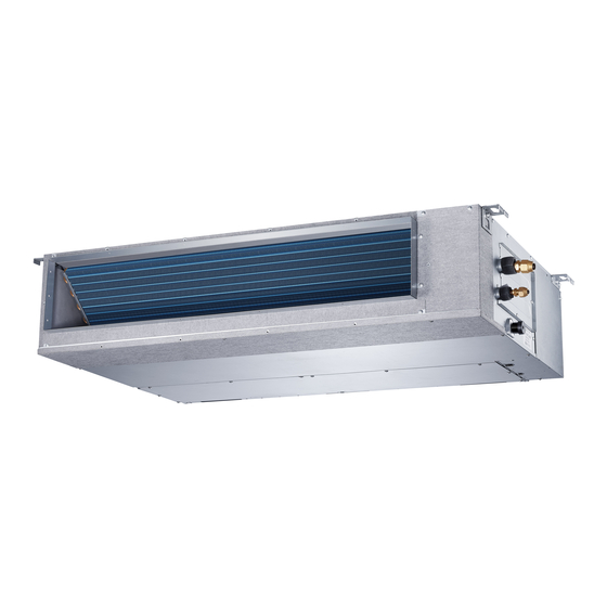
- Page 1 INSTALLATION MANUAL Ducted Unit Models B-VMH09DU-1 B-VMH12DU-1 B-VMH18DU-1 B-VMH24DU-1 517.787.2100 • www.marsdelivers.com...
- Page 2 Installation Manual - B-VMH09,12,18,24DU-1 THIS PAGE INTENTIONALLY LEFT BLANK.
-
Page 3: Table Of Contents
Installation Manual - B-VMH09,12,18,24DU-1 Table of Contents Installation Manual Accessories ............ Safety Precautions ........Installation Overview ....... Indoor Unit Installation Indoor Unit Installation ............a. Indoor Unit Parts ........b. Indoor Unit Installation Instructions ..Outdoor Unit Installation ......a. - Page 4 Installation Manual - B-VMH09,12,18,24DU-1 Refrigerant Piping Connection ....... A. Notes on Pipe Length and Elevation ....18 B. Refrigerant Piping Connection Instructions ...20 Wiring ..........a. Outdoor Unit Wiring ....b. Indoor Unit Wiring ..... c. Power Specifications ....Air Evacuation ..........
-
Page 5: Accessories
(Hitch on the connective cable between the indoor unit and outdoor unit after installation.) Owner‘s manual Installation manual Transfer connector(Φ12.7-Φ15.9)/ Φ0.5in-Φ0.63in )(Packed with the indoor unit ) NOTE: Pipe size may di er from appliance to appliance. To meet di erent pipe size requirements,... -
Page 6: Safety Precautions
Installation Manual - B-VMH09,12,18,24DU-1 Safety Precautions Read Safety Precautions Before Installation Incorrect installation due to ignoring instructions can cause serious damage or injury. The seriousness of potential damage or injuries is classified as either a WARNING or CAUTION. Failure to observe a warning may result in death. The product must be installed by installers or contractors who are licensed HVAC professionals and in compliance with all local, state and provincial laws. -
Page 7: Installation Overview
Installation Manual - B-VMH09,12,18,24DU-1 Installation Overview INSTALLATION ORDER Install the indoor unit Install the outdoor unit Install the drainpipe (Page 8) (Page 13) (Page 16) Evacuate the refrigeration system Connect the wires Connect the refrigerant pipes (Page 28) (Page 23) (Page 18) Perform a test run (Page 30) -
Page 8: Indoor Unit Parts
• Install the indoor and outdoor units, cables that can sustain its weight. If the structure is and wires at least 1m (3.2’) from televisions too weak, the unit may fall causing personal or radios to prevent static or image injury, unit and property damage, or even distortion. - Page 9 (60cmx60cm) checking orifice Fig. 4.2 Step 2: Hang indoor unit. 1. Please refer to the following diagrams to locate the four positioning screw bolt holes on the ceiling. Be sure to mark the paces where you will drill ceiling hook holes.
- Page 10 1001/39.4 1140/44.9 598/23.5 New concrete bricks Wood Place the wood mounting across the roof beam, Inlay or embed the screw bolts. (See Fig. 4.5) then install the hanging screw bolts.(See Fig.4.4) Wood mounting (Blade shape insertion) (Slide insertion) Roof beam Ceiling Fig.
- Page 11 Hanging screw bolt 2. Install and t pipes and wires after you have Fig. 4.9 nished installing the main body.When NOTE: Con rm the minimum drain tilt is 1/100 choosing where to start, determine the or more.
- Page 12 Air return ange MODLE 18-60 Ø125mm(4.92”) Ø160mm(6.3”) Ventilation panel Fig. 4.11 2. Change the mounting positions of the ventilation panel and air return ange. Ventilation panel Fig. 4.14 Step 6: Motor and drain pump maintenance (the rear ventilated panel is used as an example) Motor maintain: Take o the ventilated panel.
-
Page 13: Outdoor Unit Installation
Install the indoor and outdoor units, cables an awning for the unit. Ensure the awning and wires at least 1 meter (3.2 ft.) from does not obstruct airflow. televisions or radios to prevent static or The installation area must be dry and well √... -
Page 14: Outdoor Unit Types And Specifications
Installation Manual - B-VMH09,12,18,24DU-1 Table 5.1: Length Specifications of Split Split Type Outdoor Unit Type Outdoor Unit (unit: mm/inch) (Refer to Fig 5.4, 5.5, 5.6, 5.10 and Table 5.1) Outdoor Unit Dimensions Mounting Dimensions W x H x D Distance A Distance B 770x555x300 (30.3x21.85x11.81) -
Page 15: Notes On Drilling Hole In Wall
If the drain joint doesn’t come with a rubber seal (see Fig. 5.12 - B ), do the following: 1. Insert the drain joint into the hole in the base pan of the unit. The drain joint will click in place. -
Page 16: Drainpipe Installation
(<75mm / 3”). Installation requires a polyethylene tube (exterior diameter = 3.7-3.9cm, interior diameter Drainpipe installation for units with a pump = 3.2cm), which can be obtained at your local Ceiling hardware store or dealer. 1-1.5m <20cm... - Page 17 Installation Manual - B-VMH09,12,18,24DU-1 Units with a pump. 3. Using a 65-mm (2.5”) core drill, drill a hole in the wall. Make sure that the hole is drilled at 1. Remove the test cover. a slight downward angle, so that the outdoor Fill the water pan with 2 liters of water.
-
Page 18: Refrigerant Piping Connection
Installation Manual - B-VMH09,12,18,24DU-1 Refrigerant Piping Connection Safety Precautions Notes On Pipe Length and Elevation Ensure that the length of the refrigerant pipe, the number of bends, and the drop height between WARNING the indoor and outdoor units meets the •... - Page 19 -If oil flows back into the outdoor unit’s compressor should be maintained with suction compressor, this might cause liquid gas velocity. If velocities drop below7.62m/s compression or deterioration of oil return. (1500fpm (feet per minute)), oil return will be Oil traps in the rising gas piping can prevent decreased.
-
Page 20: Refrigerant Piping Connection Instructions
Gas side Liquid side unit (A) 1. Make sure that the pipe is cut at a perfect ” ” Φ12.7(0.5 Φ6.35(0.25 90° angle. Refer to Fig. 7.4 for examples ” ” Φ15.9(0.626 Φ9.5(0.375 of bad cuts ” ” Φ15.9(0.626 Φ9.5(0.375... - Page 21 Installation Manual - B-VMH09,12,18,24DU-1 Step 3: Flare pipe ends Table 7.5: PIPING EXTENSION BEYOND FLARE FORM Proper flaring is essential to achieve an Pipe Tightening Flare dimension (A) Flare shape torque (Unit: mm/Inch) gauge airtight seal. Min. Max. 1. After removing burrs from cut pipe, seal 18-20 N.m...
- Page 22 DO NOT bend the tubing more than 90° or more than 3 times. Bend the pipe with thumb min-radius 10cm (3.9”) Fig. 7.11 6. After connecting the copper pipes to the indoor unit, wrap the power cable, signal cable and the piping together with binding tape.
-
Page 23: Wiring
Be sure to use H07RN-F cables. is made through a switch that disconnects all poles, with contact gap of at least 3mm (0.118”). Table 8.1: Minimum Cross-Sectional Area DO NOT modify the length of the power of Power Cables in North America •... -
Page 24: Indoor Unit Wiring
Using wire strippers, strip the rubber jacket 0.75 from both ends of the signal cable to reveal ≤ about 15cm (5.9”) of the wire. 6 - 10 b. Strip the insulation from the ends of the 10 - 16 wires. - Page 25 Installation Manual - B-VMH09,12,18,24DU-1 CAUTION While connecting the wires, please strictly • - Press “CONFIRM”. The air conditioning follow the wiring diagram. unit will then start the fan for air ow The refrigerant circuit can become very • automatic adjustment. hot.
-
Page 26: Power Specifications
Installation Manual - B-VMH09,12,18,24DU-1 Power Specifications NOTE: Electric auxiliary heating type circuit breaker/fuse need to add more than 10 A. Indoor Power Supply Specifications ≤18K MODEL(Btu/h) 19K~24K 25K~36K PHASE 1 Phase 1 Phase 1 Phase POWER VOLT 208-240V 208-240V 208-240V CIRCUIT BREAKER/ 25/20 32/25... - Page 27 Installation Manual - B-VMH09,12,18,24DU-1 Inverter Type A/C Power Specifications ≤18K MODEL(Btu/h) 19K~24K 25K~36K PHASE 1 Phase 1 Phase 1 Phase POWER (indoor) VOLT 220-240V 220-240V 220-240V CIRCUIT BREAKER/ 15/10 15/10 15/10 FUSE(A) PHASE 1 Phase 1 Phase 1 Phase POWER (outdoor) 208-240V 208-240V 208-240V...
-
Page 28: Air Evacuation
-0.1MPa, check if there is a gas leak or water 8. Insert hexagonal wrench into the packed valve inside the pipe. If there is no leak, perform (high pressure valve) and open the valve by another evacuation for 1 or 2 hours. -
Page 29: Note On Adding Refrigerant
For example, in North America, the standard pipe length is 7.5m (25’) In other areas, the standard pipe length is 5m (16‘). The additional refrigerant to be charged can be calculated using the following formula: Liquid Side Diameter φ6.35(1/4”) -
Page 30: Test Run
Installation Manual - B-VMH09,12,18,24DU-1 Test Run f. Check to see that the drainage system is Before Test Run unimpeded and draining smoothly. A test run must be performed after the entire g. Ensure there is no vibration or abnormal system has been completely installed. Confirm noise during operation. - Page 31 Installation Manual - B-VMH09,12,18,24DU-1 THIS PAGE INTENTIONALLY LEFT BLANK.
- Page 32 11/2019...
Need help?
Do you have a question about the . and is the answer not in the manual?
Questions and answers