
Related Manuals for Endress+Hauser Turbimax W CUS65


Summary of Contents for Endress+Hauser Turbimax W CUS65
- Page 1 Operating Instructions Turbimax W CUS65 Turbidity sensor BA370C/07/en/01.08 71067680...
- Page 2 Endress+Hauser...
-
Page 3: Table Of Contents
Turbimax W CUS65 Table of contents Safety instructions ....4 Designated use ......4 Installation, commissioning and operation . -
Page 4: Safety Instructions
Safety instructions Designated use The Turbimax W CUS65 sensor is used for optical turbidity and solids content measurement. Due to various sensor heads the sensor is suitable for use from low to high concentration ranges. • Wastewater clarification / sludge treatment •... -
Page 5: Return
Turbimax W CUS65 Safety instructions Return If the sensor has to be repaired, please return it cleaned to the sales center responsible. Please use the original packaging, if possible. Please enclose the completed "Declaration of Hazardous Material and De-Contamination" (copy the second last page of these Operating Instructions) with the packaging and the transportation documents. -
Page 6: Identification
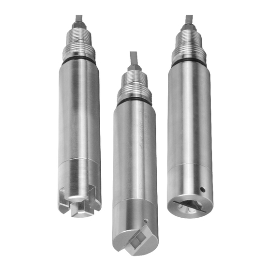
Identification Turbimax W CUS65 Identification Product structure Measuring range, application 0 to 12 g/l, activated sludge, centrate 0 to 40 g/l, return sludge 0 to 50 g/l, primary sludge, digested sludge 1 to 1000 FNU, wastewater effluent, service water, condensate, boiler feedwater... -
Page 7: Installation
Turbimax W CUS65 Installation Installation Incoming acceptance, transport, storage • Make sure the packaging is undamaged! Inform the supplier about damage to the packaging. Keep the damaged packaging until the matter has been settled. • Make sure the contents are undamaged! Inform the supplier about damage to the delivery contents. - Page 8 Installation Turbimax W CUS65 3.2.2 Wall distance Installing the sensor in pipework or very close to the wall can cause backscatter which results in a higher sensor signal. The effective wall or bottom distance can be optimized by aligning the flat sensor side.
- Page 9 Turbimax W CUS65 Installation Installation angle α dependent on sensor version: • CUS65-A: 80° • CUS65-B: 90° • CUS65-C, E: 100° • CUS65-D: 110° a0008990 Fig. 4: Installation with retractable assembly Arrow = flow direction of the medium 3.2.4 Immersion operation Note! •...
-
Page 10: Installation Instructions
Turbimax W CUS65 Installation instructions 3.3.1 Measuring system A complete measuring system comprises: • Turbidity transmitter CUM740 • Turbidity sensor Turbimax W CUS65 • Immersion pipe CYY105 or • Retractable assembly Cleanfit CUA451 • Extension cable (optional) • Junction box (optional) a0008988 a0008989 Abb. -
Page 11: Post-Installation Check
Turbimax W CUS65 Wiring Post-installation check Checks Info In general: Optical windows free of film? If no: cleaning (--> "Maintenance") Permissible orientation observed? --> "Installation conditions" Medium present? Is the assembly or piping completely filled with medium? Immersion assembly: Do not use the sensor suspended freely from the cable. -
Page 12: Commissioning
Commissioning Turbimax W CUS65 Commissioning Function check Before first commissioning, check if: • the sensor is correctly installed • the electrical connection is correct. Warning! Danger of medium leaking off Before applying compressed air to an assembly with cleaning facility, make sure the connections are correctly fitted. -
Page 13: Accessories
Turbimax W CUS65 Accessories Accessories Assemblies Retractable assembly Cleanfit CUA451 • retractable assembly with ball valve; for turbidity sensors; material: stainless steel • ordering acc. to product structure (Technical Information TI369C/07/en) Immersion assembly CYY105 • For sensor immersion in basins •... -
Page 14: Connection Accessories
Accessories Turbimax W CUS65 Connection accessories Extension cable • Extension cable length 10m (32 ft) • Shielded, with SXP plug and SXK coupling • Ingress protection IP 67 • Order No.: 51503633 Plugs • SXP plug – 7-pole – Order No.: 51504027 •... -
Page 15: Troubleshooting
Turbimax W CUS65 Troubleshooting Troubleshooting Troubleshooting instructions Troubleshooting must take account of the whole measuring system: • Transmitter • Electrical leads and connectors • Assembly • Sensor The possible causes of failure listed in the following table primarily refer to the sensor. -
Page 16: Technical Data
Technical data Turbimax W CUS65 Technical data Input Measured variable Turbidity Measuring range Version Measuring range Application CUS65-A 0 to 12 g/l Activated sludge, centrate CUS65-B 0 to 40 g/l Return sludge CUS65-C 0 to 50 g/l Primary sludge, digested sludge... -
Page 17: Process
Turbimax W CUS65 Technical data Process Process temperature range 0 to 50 °C (32 to 120 °F) Process pressure 1 to 6 bar (15 to 87 psi) Temperature pressure diagram °F °C a0008127 Fig. 12: Temperature pressure diagram Flow No minimum flow required. -
Page 18: Index
Turbimax W CUS65 Index Accessories Performance characteristics......16 Transmitter....... . . 13 Pipework . - Page 19 Erklärung zur Kontamination und Reinigung Please reference the Return Authorization Number (RA#), obtained from Endress+Hauser, on all paperwork and mark the RA# clearly on the outside of the box. If this procedure is not followed, it may result in the refusal of the package at our facility.
- Page 20 www.endress.com/worldwide BA370C/07/en/01.08 Printed in Germany / FM+SGML 6.0 / DT 71067680...
Need help?
Do you have a question about the Turbimax W CUS65 and is the answer not in the manual?
Questions and answers