Table of Contents
Advertisement
Installer: Leave this manual with the appliance. Consumer: Retain this manual for future reference.
READ INSTRUCTIONS CAREFULLY: YOUR SAFETY IS IMPORTANT TO YOU AND TO OTHERS.
Read and follow all instructions. Place instructions in a safe place for future reference. Do not
allow anyone who has not read these instructions to assemble, light, adjust or operate the
heater.
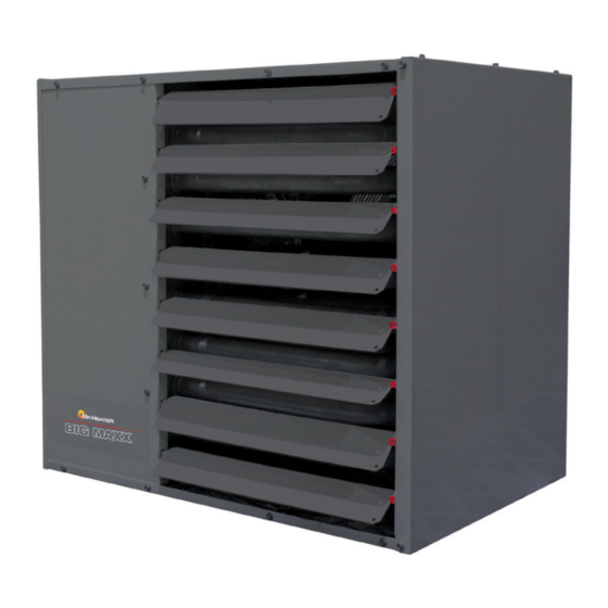
LARGE UNIT HEATER
FOR RESIDENTIAL/COMMERCIAL USE
WARNING: Improper installation, adjustment, alteration, service or maintenance can cause
injury or property damage. Refer to this manual. For assistance or additional information
consult a qualified installer, service agency or the gas supplier.
-WHAT TO DO IF YOU SMELL GAS
Ǟ DO NOT try to light appliance.
Ǟ DO NOT touch any electrical switch, do not use any phone in your building
Ǟ Leave the building immediately
Ǟ Immediately call your gas supplier from a phone remote from the building. Follow the gas
suppliers instructions
Ǟ If you cannot reach your gas supplier, call the Fire Department.
- Installation and service must be performed by a qualified installer, service agency or the gas
supplier.
FOR YOUR SAFETY:
Do not store or use gasoline or other flammable vapors and liquids in the vicinity of this or any
other appliance.
WARNING: If the information in these instructions are not followed exactly, a fire or explosion
may result causing property damage, personal injury or loss of life.
OPERATING INSTRUCTIONS
AND OWNER'S MANUAL
www.mrheater.com
800-25 1-0001
•
MODEL#
MHU200NG
MHU250NG
MHU300NG
MHU400NG
60339
Advertisement
Table of Contents

Subscribe to Our Youtube Channel
Related Manuals for MrHeater MHU200NG


Summary of Contents for MrHeater MHU200NG
- Page 1 Installer: Leave this manual with the appliance. Consumer: Retain this manual for future reference. MODEL# OPERATING INSTRUCTIONS MHU200NG AND OWNER’S MANUAL MHU250NG MHU300NG MHU400NG READ INSTRUCTIONS CAREFULLY: YOUR SAFETY IS IMPORTANT TO YOU AND TO OTHERS. Read and follow all instructions. Place instructions in a safe place for future reference. Do not allow anyone who has not read these instructions to assemble, light, adjust or operate the heater.
-
Page 2: Table Of Contents
OF CALIFORNIA TO CAUSE CANCER AND BIRTH cause birth defects or other reproductive harm, for more DEFECTS OR OTHER REPRODUCTIVE HARM. FOR MORE information go to www.P65Warnings.ca.gov INFORMATION VISIT WWW.P65WARNINGS.CA.GOV MHU200NG MHU250NG MHU300NG MHU400NG V/A/H/Phase 120v / 6.3A / 60hZ / 1Ø... - Page 3 120VAC power. For specific information on each model, see Table 1. Dimensional Data Top View Rear View Width Width FIGURE 1 BTU input BTU output Size [BTU/HR] [BTU/HR] WIDTH LENGTH HEIGHT WEIGHT[Lbs.] MHU200NG 200,000 160,000 41.3” 28.7” 24.8” MHU250NG 250,000 200,000 41.3” 28.7” 24.8” MHU300NG 300,000 240,000 41.3”...
- Page 4 These units are CSA International design certified. These unit heaters SHIPPING are certified for installation to combustible material as listed in Table The heater is completely assembled. Installation instructions, two 3 and on unit rating plate. Accessibility and service clearances must be mounting brackets (shipped loose), and a flue transition are included.
-
Page 5: Introduction
IN UNITED STATES: Refer to Standard for Aircraft Hangars, ANSI/ Clearances To Combustibles NFPA 409 (latest edition). Front View 1. In aircraft storage and servicing areas, heaters shall be installed at least 10 ft. (3 m) from above the upper surface of wings or of the engine enclosures of the highest aircraft that may be housed in the Access Non-Access... -
Page 6: Installation
All installation and service of these units must be performed by a Heater Subcomponents qualified installation and service agency only as defined in ANSI Z223.1 (NFPA 54) - latest edition or in Canada by a licensed gas fitter. High Limit Switch Draft Inducer This unit is certified with the controls furnished. - Page 7 Determine that there is not blockage, restriction, leakage, corrosion, CAUTION: Do not install units below 7’ measured from the or other deficiencies that can cause hazards. The vent pipe should bottom of the unit to the floor in commercial applications be corrosion-resistant galvanized steel of a thickness that meets the (unless unit is properly guarded to provide user protection National Fuel Gas Code.
- Page 8 How to attach a single wall vent terminal to double wall (Type B) vent Model Vent Pipe pipe: Minimum Maximum Diameter 1. Look for the “flow” arrow on the vent pipe. MHU200NG 4” 3’ 70’ 2. Slide the vent terminal inside the exhaust end of the double wall MHU250NG vent pipe. MHU300NG 6”...
- Page 9 Fuel Gas Code, ANSI Z223.1 or (Canada) CAN/CGA-B149 Installation Venting Through Combustible Roof or Wall Code. The vent must extend at least 5’ (1.6m) above the highest connected equipment flue collar. Specified HORIZONTAL VENTING Terminal An appliance that operates with a positive vent static pressure and with a vent gas temperature that avoids excessive condensate production in the vent is said to be ‘Category III’.
- Page 10 Additional requirements for horizontal venting: caused by exhaust fans, etc. If sufficient quantities of combustion air are not available, the heater or another appliance will operate in an in- • Category III venting systems may NOT be common vented, and no efficient manner, resulting in incomplete combustion which can result other gas units are allowed to be vented into it.
- Page 11 # of Consump- Connection Pressure min. Pressure max. Pressure Size Orifices tion [“] [“ W.C.] [“ W.C.] [“ W.C.] [“] [CFH] MHU200NG 0.110 190.5 MHU250NG 0.110 238.1 MHU300NG 1.73 0.138 285.7 MHU400NG 2.13 0.138 380.9 TABLE 5: Natural Gas Consumption *Assumes an average heating value of 1050 BTU/SCF and a Specific Gravity of 0.60.
- Page 12 LEAK TESTING For leak testing on pressures above 20 inches W.C.: When leak testing with pressures above 20 inches W.C., the unit must WARNING: Use a soap solution or equivalent for leak testing. be isolated from the supply pipe. Close the field installed manual shut Never test for leak with an open flame such as with matches off valve, disconnect the supply line to the unit, and temporarily cap or candles.
- Page 13 Altitude 0-2000 ft. (0-610m) Altitude 2000-3000 ft. (610-910mm) Manifold Pressure Input Rating Manifold Pressure Input Rating Model [“ W.C.] [kPa] [BTU/Hr] [“ W.C.] [kPa] [BTU/Hr] MHU200NG 1.12 200,000 58,614 4.15 1.03 192,000 56,269 MHU250NG 1.22 250,000 73,268 4.52 1.12...
- Page 14 • The power supply to the unit must be protected with a fused or circuit breaker switch, so that power can be turned off for servicing. Power Supply [Hz] [Ph] MHU200NG MHU250NG MHU300NG 1,200 MHU400NG 1,200 TABLE 9: Electrical Specifications External electrical service connections that must be installed include: a.
- Page 15 Main Components Line Voltage Thermostat Wiring Connector on Heater FIGURE 10 Large Unit Heater Operating Instructions and Owner’s Manual...
- Page 16 Internal Wiring Diagram FIGURE 11 Large Unit Heater Operating Instructions and Owner’s Manual...
-
Page 17: Start-Up
• Connect wires together with UL approved wire connectors. Line Voltage Field Wiring NOTICE: A UL Listed switch may be installed in the 2x4 junction box for use as a service disconnect. CAUTION: Route the field supplied power wires so that they do not come in contact with the flue wrapper or venter housing. - Page 18 • The proper mounting height is observed for the application. The minimum and maximum inlet gas supply pressure are indicated in Table 5 and in Table 6. • All clearance to combustible distances or service clearances are maintained. Verify minimum inlet gas supply pressure: •...
- Page 19 Prior to Leaving Job Site The target manifold gas supply pressure is indicated in Table 5 and Table 6 : Prior to leaving the job site, verify that: NOTICE: Manifold pressure of the heater is pre-set at the factory. No •...
- Page 20 Flame Lost Sequence Call for heat Start-Up Failed Pressure Switch Condition Change Sequence Call for heat Failed Combustion Air Flow Monitoring Sequence Call for heat SEQUENCE OF OPERATION 7. Turn on electrical power to unit. 8. Set the thermostat to desired setting. 1.
-
Page 21: Maintenance
MAINTENANCE FLUE PASSAGEWAY AND FLUE BOX The flue passages and flue box should be inspected and cleaned CAUTION: Turn off gas and electrical power to unit before prior to each heating season. The sequence of operation should be as performing any maintenance or service operations on this follows: unit. -
Page 22: Fuel Conversion Instructions
FUEL CONVERSION INSTRUCTIONS The heater is standard manufactured for operation with natural gas. In case of use with LP /propane gas, use the conversion orifices supplied with the unit. Follow the instructions below. Position of the Manifold Screws 4 Screws FIGURE 14 Rotation of the Valve/Manifold Assembly ROTATE valve/manifold... - Page 23 Step 5 WARNING: Explosion Hazard Rotate the valve/ manifold assembly back up into the burner box, TURN OFF THE GAS SUPPLY TO THE HEATER making sure that all the orifices are indexed into the burners and are BEFORE PERFORMING ANY SERVICE OR MAINTE- not caught on the locating ring on the back of each burner.
-
Page 24: Troubleshooting Guide
TROUBLESHOOTING GUIDE NOTICE: Bypassing any switch is intended for testing purposes only. Do not leave switch bypassed during normal operation or the heater’s built- in safety mechanisms will be compromised. Symptom Possible Cause Corrective Action The draft inducer motor The air circulating fan does not turn on immediately. Limit switch is open or pressure switch is does not turn on stuck closed. - Page 25 Symptom Possible Cause Corrective Action The burners do not stay lit The burners light and then shut off immediately (within Check inlet pressure and limit switches. 1-2 seconds). The burner does not stay on for approximately 8-10 Check control board for flash codes. seconds, and then shut off.
-
Page 26: Parts List
PARTS LIST When ordering parts include the complete unit model number listed on the unit rating plate. Mr. Heater • Large Unit Heater • Model # MHU200NG / MHU250NG / MHU300NG/ MHU400NG Liquid Propane to Natural Gas Conversion Kit Natural Gas to Liquid Propane Conversion Kit MHU200NG..............F260165... - Page 27 PARTS LIST SEE BACK PAGE FOR PARTS ORDERING INFORMATION Description 200NG 250NG 300NG 400NG HEAT EXCHANGER 60320 60321 60322 60323 UPPER SIDE PANEL 60324 60324 60324 60324 LATERAL SIDE PANEL 1 60325 60325 60326 60327 LOUVER 60328 60328 60328 60328 LATERAL SIDE PANEL 2 60329 60329...
-
Page 28: Warranty
OPERATING INSTRUCTIONS MODEL# MHU200NG AND OWNER’S MANUAL MHU300NG MHU250NG MHU400NG READ INSTRUCTIONS CAREFULLY: YOUR SAFETY IS IMPORTANT TO YOU AND TO OTHERS. Read and follow all instructions. Place instructions in a safe place for future reference. Do not allow anyone who has not read these instructions to assemble, light, adjust or operate the heater.
Need help?
Do you have a question about the MHU200NG and is the answer not in the manual?
Questions and answers