Table of Contents
Advertisement
Advertisement
Table of Contents

Related Manuals for Leica Geosystems GS14


Summary of Contents for Leica Geosystems GS14
- Page 1 Leica GS14/GS16 User Manual Version 5.0 English...
- Page 2 Logo is a trademark of SD-3C, LLC. • All other trademarks are the property of their respective owners. Validity of this This manual applies to all models of the Leica GS14/GS16 GNSS instrument. manual Where there are differences between the various instruments they are clearly described.
- Page 3 Leica Geosystems On the last page of this manual, you can find the address of Leica Geosystems address book headquarters. For a list of regional contacts, please visit http://leica-geosystems.com/contact-us/sales_support. myWorld@Leica Geosystems (https://myworld.leica-geosystems.com) offers a wide range of services, information and training material.
-
Page 4: Table Of Contents
Batteries 4.2.1 Operating Principles 4.2.2 Battery for GS14/GS16 Working with the Memory Device Working with the RTK Device LED Indicators on GS14/GS16 Guidelines for Correct Results with GNSS Surveys Care and Transport Transport Storage Cleaning and Drying Technical Data GS14/GS16 Technical Data 6.1.1... -
Page 5: Safety Directions
Safety Directions General Introduction Description The following directions enable the person responsible for the product, and the person who actually uses the equipment, to anticipate and avoid operational hazards. The person responsible for the product must ensure that all users understand these directions and adhere to them. -
Page 6: Definition Of Use
• Use of products with recognisable damages or defects. Use with accessories from other manufacturers without the prior explicit • approval of Leica Geosystems. Inadequate safeguards at the working site. • Controlling of machines, moving objects or similar monitoring application •... -
Page 7: Responsibilities
• To be familiar with local regulations relating to safety and accident preven- • tion. To inform Leica Geosystems immediately if the product and the application • becomes unsafe. • To ensure that the national laws, regulations and conditions for the opera- tion of the product are respected. - Page 8 WARNING Distraction/loss of attention During dynamic applications, for example stakeout procedures, there is a dan- ger of accidents occurring if the user does not pay attention to the environ- mental conditions around, for example obstacles, excavations or traffic. Precautions: ▶ The person responsible for the product must make all users fully aware of the existing dangers.
- Page 9 DANGER Risk of being struck by lightning If the product is used with accessories, for example on masts, staffs, poles, you may increase the risk of being struck by lightning. Danger from high vol- tages also exists near power lines. Lightning, voltage peaks, or the touching of power lines can cause damage, injury and death.
- Page 10 Grounding the instrument/antenna Antenna Lightning conductor array Antenna/instrument connec- tion Metallic mast Connection to earth GS_040 WARNING Inappropriate mechanical influences to batteries During the transport, shipping or disposal of batteries it is possible for inappro- priate mechanical influences to constitute a fire hazard. Precautions: ▶...
- Page 11 WARNING Electric shock due to missing ground connection If unit is not connected to ground, death or serious injury can occur. Precautions: ▶ The power cable and power outlet must be grounded! ☞ The following advice is only valid for power adapter and car adapter. WARNING Electric shock due to use under wet and severe conditions If unit becomes wet it may cause you to receive an electric shock.
-
Page 12: Electromagnetic Compatibility Emc
Electromagnetic radiation can cause disturbances in other equipment. Precautions: ▶ Although the product meets the strict regulations and standards which are in force in this respect, Leica Geosystems cannot completely exclude the possibility that other equipment may be disturbed. Safety Directions... - Page 13 Although the product meets the strict regulations and standards which are in force in this respect, Leica Geosystems cannot completely exclude the possibil- ity that function of the product may be disturbed in such an electromagnetic environment.
-
Page 14: Fcc Statement, Applicable In U
Precautions: ▶ Although the product meets the strict regulations and standards which are in force in this respect, Leica Geosystems cannot completely exclude the possibility that other equipment can be disturbed or that humans or ani- mals can be affected. - Page 15 Labelling GS14 008606_002 Labelling GS16 Model: GS16 Equip. No.:12345678 Leica Geosystems AG, CH-9435 Heerbrugg Manufactured: 20XX, Made in Switzerland Power: 12V nominal / 700 mA max. Contains: FCC ID Q2331308 / 6850A-31308 QIPPHS8-P / 7830A-PHS8P 0012204_001 Labelling internal Type: GEB212 Art.
-
Page 16: Ices-003 Statement, Applicable In Canada
ICES-003 Statement, Applicable in Canada WARNING This Class (B) digital apparatus complies with Canadian ICES-003. Cet appareil numérique de la classe (B) est conforme à la norme NMB-003 du Canada. Canada Compliance Statement This device complies with Industry Canada’s license-exempt RSSs. Operation is subject to the following two conditions: This device may not cause interference;... -
Page 17: Description Of The System
75% full before beginning the upload, and do not remove the battery during the upload process. Software Description All GS models The software can be uploaded using the Leica Web server application or myWorld@Leica Geosystems. Description of the System... -
Page 18: Power Concept
GS GNSS instrument is switched off. ☞ microSD cards can, with the supplied adaptor, also be used in an OMNI drive as supplied by Leica Geosystems. Other PC card drives can require an adaptor. Description of the System... -
Page 19: Container Contents
Container Contents Container for GS instrument and accessories 1/2 009340_001 GHT63 clamp Manuals and USB documentation card GEB212 or GEB311 batteries Antenna GAT18 mobile antenna GAT21, GAT25 or GAT26 radio antenna Tribrach CS15 field controller with GHT62_only holder or CS20 field controller with GHT66 holder or CS35 tablet Height hook Cables... -
Page 20: Instrument Components
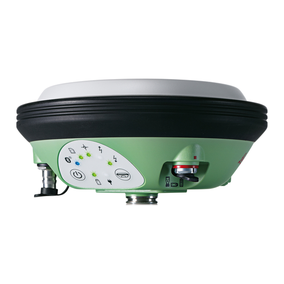
Turn on the instrument by holding down the Power key for 2 s. A green blinking light at both power LEDs indi- cates that the instrument powers up. GS14/GS16 QN-connector for external components... -
Page 21: User Interface
Rover LEDs shine red, both Power and the Bluetooth LEDs shine yellow and then are turned off. Function button ☞ All functions following described assume the GS14/GS16 is already Button Function Function Press and hold button for <1 s. If the GS14/GS16 is in: Base mode: •... -
Page 22: Operating Principles
After deleting the registry, the GNSS instrument is turned off. Operating Principles Operating the The GS14/GS16 GNSS instrument is operated either by the pressing its buttons instrument (ON/OFF button, function button) or by the field controller. User Interface... - Page 23 Operation by buttons The GS14/GS16 GNSS instrument is operated by pressing its buttons. Refer to "3.1 Keyboard" for a detailed description of the buttons and their function. Operation by field controller The GS14/GS16 GNSS instrument is operated by the field controller using the Leica SmartWorx Viva/Leica Captivate software.
-
Page 24: Operation
Operation Equipment Setup 4.1.1 Setting up as a Post-Processing Base The equipment setup described is used for static operations over markers. Description The instrument can be programmed with the field controller before use which can then be omitted from the setup. ☞... -
Page 25: Setting Up As A Real-Time Base
The GS14/GS16 instrument can be programmed with the field controller before use which can then be omitted from the setup. The connection between GS14/GS16 and the field controller is made via Blue- tooth. The radio antenna is mounted on the antenna arm which clips to the GNSS antenna. - Page 26 ☞ The GNSS antenna is mounted directly using screw fitting. If using stub and • adapter, procedures can vary slightly. When using the adapter and carrier, ensure that the antenna and the • adapter assembly slide down the full length of the carrier stub. An incor- rectly mounted antenna will have a direct effect on the results.
- Page 27 GHT58 tripod bracket GEV264 Y-cable GFU radio modem GEB371 external battery SD card CompactFlash card CS15 field controller GEB212 battery CS20 field controller GEB331 battery CS35 field controller USB stick Equipment setup - GS14/GS16 GSM/ UMTS or GS14/GS16 UHF 004570_003 Operation...
- Page 28 GS14/GS16 instrument with integrated GSM/UMTS modem or UHF (transmit) modem microSD card GEB212 battery GRT146 carrier Tribrach GAT1/GAT2 radio antenna GAD108 arm, for UHF use only Height hook Tripod GHT61 hand strap SD card CompactFlash card Utility hook CS20 field controller...
-
Page 29: Setting Up As A Real-Time Rover
Connections are made to the GNSS antenna, radio antenna and field controller. The field controller is fixed to the pole with the GHT62. Connection between the GS14/GS16 instrument and the field controller is made through Bluetooth. ☞ The antenna is mounted directly using screw fitting. If using stub and •... - Page 30 Equipment setup 002497_004 GNSS antenna Pole CompactFlash card SD card CGR radio CS15 field controller GEB212 battery GHT62 holder GHT63 pole clamp CS20 field controller GEB331 battery GHT66 holder CS35 tablet USB stick GHT78 holder microSD card Operation...
- Page 31 Equipment setup - GS14/GS16 UHF 005658_002 GS14/GS16 GNSS antenna with integrated UHF radio modem GAT1/GAT2 radio antenna GAD108 arm CompactFlash card SD card CS15 field controller GEB212 battery GHT62 holder GHT63 pole clamp CS20 field controller GEB331 battery GHT66 holder...
-
Page 32: Fixing The Field Controller To A Holder And Pole
Press ON/OFF button on the field controller to switch on. Insert the data storage device and the batteries into the GS14/GS16. Press ON/OFF button on the GS14/GS16 to switch on. Screw the GS14/GS16 to the top of the pole. -
Page 33: Connecting To A Personal Computer
Apply slight pressure in a downward direction and then lower the top part of the CS field controller until the unit is clicked into the holder. The guides of the mounting plate aid in this action. 008547_001 After the CS field controller is placed onto the mounting plate, ensure that the locking pin is put into the locked position. - Page 34 Name Description GEV223 USB data cable, 1.8 m, connects instrument to Mini-USB to GEV234 USB data cable, 1.65 m, connects CS to GS or CS to PC (USB) GEV261 Y-cable, 1.8 m, connects instrument to PC – battery Uninstalling the ☞...
- Page 35 The Welcome to InstallShield Wizard for Leica GS, TS/TM/MS, CS and GR USB drivers window appears. ☞ Ensure that all Leica devices are disconnected from your PC before you continue! Next>. The Ready to Install the Program window appears. Install. The drivers will be installed on your PC. The InstallShield Wizard Completed window appears.
-
Page 36: Connecting To The Web Server
Type the IP address of the device into the search field. \\192.168.254.1\ for field controller • \\192.168.254.3\ for other instruments • Press Enter. A file browser opens. You can now browse within the folders on the instrument. 4.1.6 Connecting to the Web Server Description The Web server is a web-based tool to view the status of and configure the GNSS instruments. - Page 37 Establishing a Bluetooth connection between PC and GS GNSS instru- ment Start the PC and turn on the GS GNSS instrument. ☞ Instead of connecting to your PC, you can connect your GS GNSS instrument to the field controller. In this case, turn on the field controller, start Leica SmartWorx Viva/Leica Captivate and establish a Bluetooth connection to the GS GNSS instrument.
-
Page 38: Batteries
It is normal for the battery to become warm during charging. Using the • chargers recommended by Leica Geosystems, it is not possible to charge the battery once the temperature is too high. For new batteries or batteries that have been stored for a long time •... -
Page 39: Working With The Memory Device
Push the slide fastener in the direction of the arrow with the close- lock symbol. Working with the RTK Device Devices fitted into Depending on the GS14/GS16 model one or two of the following devices are the GS14/GS16 GNSS integrated: instrument... -
Page 40: Led Indicators On Gs14/Gs16
Insert and remove a SIM card step-by-step 008656_001 ☞ Inserting/removing the SIM card while the GS14/GS16 is turned on can result in permanent damage to the card. Only insert/remove the SIM card when the GS14/GS16 is switched off. ☞ The SIM card is inserted into a slot inside the battery compartment. - Page 41 5% mem- ory left. microSD card is full, no raw data is being log- ged or no microSD card is inserted but GS14/ GS16 is configured to log raw data. Position LED no satellites are tracked or GS14/GS16 is switched off.
-
Page 42: Guidelines For Correct Results With Gnss Surveys
IF the THEN flashing GS14/GS16 is in rover mode. RTK data is green being received at the interface of the com- munication device. RTK Base LED GS14/GS16 is in RTK rover mode or GS14/ GS16 is switched off. green GS14/GS16 is in RTK base mode. No RTK data is being passed to the interface of the communication device. -
Page 43: Care And Transport
Shipping When transporting the product by rail, air or sea, always use the complete orig- inal Leica Geosystems packaging, container and cardboard box, or its equiva- lent, to protect against shock and vibration. Shipping, transport of When transporting or shipping batteries, the person responsible for the prod-... - Page 44 Cables and plugs Keep plugs clean and dry. Blow away any dirt lodged in the plugs of the con- necting cables. Connectors with dust Wet connectors must be dry before attaching the dust cap. caps Care and Transport...
-
Page 45: Technical Data
Technical Data GS14/GS16 Technical Data 6.1.1 Tracking Characteristics GS14 Satellite reception Dual frequency Supported signals System Signal L1 C/A, L2P, L2C GLONASS L1 C/A, L2P, L2C Galileo E1, E5b BeiDou B1, B2 ☞ Carrier phase and code measurements on L1 and L2 are fully independent with AS on or off. -
Page 46: Technical Data
1 GB is sufficient for over 1 year of raw data logging based on logging every 15 s from an average of 15 satellites. Power Power consumption: GS14, radio excluded: 2.6 W typically, 220 mA (with external battery), 350 mA (with internal battery) GS16, radio excluded: 3.1 W typically,... - Page 47 Capacity GEB371 Li-Ion 13 V 16.8 Ah Operating times The given operating times are valid for GS14/GS16: instrument; one fully charged GEB212 battery. • • room temperature. Operating times will be shorter when working in cold weather. Type Radio Digital cellular...
- Page 48 Type GS14 GS16 Galileo AltBOC 1191.795 MHz ü BeiDou B1 1561.098 MHz ü ü BeiDou B2 1207.14 MHz ü ü QZSS L1 1575.42 MHz ü QZSS L2 1227.60 MHz ü QZSS L5 1176.45 MHz ü Gain (LNA) Typically Typically 22 dB...
-
Page 49: Conformity To National Regulations
Hereby, Leica Geosystems AG declares that the radio equipment type • GS14/GS16 is in compliance with Directive 2014/53/EU and other appli- cable European Directives. The full text of the EU declaration of conformity is available at the fol- lowing Internet address: http://www.leica-geosystems.com/ce. -
Page 50: Dangerous Goods Regulations
6.2.2 Dangerous Goods Regulations Dangerous Goods Many products of Leica Geosystems are powered by Lithium batteries. Regulations Lithium batteries can be dangerous under certain conditions and can pose a safety hazard. In certain conditions, Lithium batteries can overheat and ignite. -
Page 51: Software Licence Agreement
Leica Geosystems. Such software is protected by copyright and other laws and its use is defined and regulated by... -
Page 52: Appendix A Pin Assignments And Sockets
Appendix A Pin Assignments and Sockets Description Some applications require knowledge of the pin assignments for the instru- ment ports. In this chapter, the pin assignments and sockets for the instrument ports are explained. Ports at the instrument underside QN-connector, only for mod- els with UHF radio Port 1 (USB and serial) 004118_002... - Page 54 798165-5.0.0en Original text (798165-5.0.0en) Published in Switzerland © 2018 Leica Geosystems AG, Heerbrugg, Switzerland Leica Geosystems AG Heinrich-Wild-Strasse CH-9435 Heerbrugg Switzerland Phone +41 71 727 31 31 www.leica-geosystems.com...
Need help?
Do you have a question about the GS14 and is the answer not in the manual?
Questions and answers