A.O. Smith DSE-5 Instruction Manual
Commercial electric water h
Hide thumbs
Also See for DSE-5:
- Installation and operaion manual (24 pages) ,
- Description, operation, installation and maintenance manual (47 pages)
Table of Contents
Advertisement
Quick Links
Instruction Manual
coMMercIal electrIc water heaters
Models dse-5 thru dse-120
InstallatIon - operatIon - serVIce -
MaIntenance - lIMIted warranty
A DIVISION OF A. O. SMITH CORPORATION
RENTON, WASHINGTON
www.hotwater.com
asMe
Thank you for buying this energy efficient water
heater. We appreciate your confidence in our
products.
place these InstructIons adjacent to heater and notIfy owner to keep for future reference.
PRINTED 0909
198334-001
Advertisement
Table of Contents

Subscribe to Our Youtube Channel
Related Manuals for A.O. Smith DSE-5


Summary of Contents for A.O. Smith DSE-5
- Page 1 Instruction Manual coMMercIal electrIc water heaters Models dse-5 thru dse-120 InstallatIon - operatIon - serVIce - MaIntenance - lIMIted warranty A DIVISION OF A. O. SMITH CORPORATION RENTON, WASHINGTON www.hotwater.com asMe Thank you for buying this energy efficient water heater. We appreciate your confidence in our products.
-
Page 2: Safe Installation, Use And Service
safe InstallatIon, use and serVIce Your safety and the safety of others is extremely important in the installation, use, and servicing of this water heater. Many safety-related messages and instructions have been provided in this manual and on your own water heater to warn you and others of a potential injury hazard. -
Page 3: General Safety Information
General safety InforMatIon precautIons hydroGen Gas (flaMMaBle) DO NOT USE THIS APPLIANCE IF ANY PART HAS BEEN UNDER WATER. Immediately call a qualified service technician to inspect the appliance and to replace any part of the control system which has been under water. If the unit is exposed to the following, do not operate heater until all corrective steps have been made by a qualified service agency. -
Page 4: Table Of Contents
taBle of contents SAFE INSTALLATION, USE AND SERVICE............2 TEMPERATURE REGULATION ................16 GENERAL SAFETY INFORMATION ...............3 High Temperature Limit Controls (ECO) ............16 Precautions ....................3 Thermostat Controls ..................16 Hydrogen Gas (Flammable) ................3 Temperature Adjustment ................16 TABLE OF CONTENTS ...................4 CONTROL SYSTEM OPERATION ...............17 INTRODUCTION .....................4 Heating Element Operation ................17 Preparing for the Installation ................4... -
Page 5: Dimensions And Capacities Data
dIMensIons and capacItIes data Tank Capacity All Dimensions in Inches (mm) Approximate Shipping Wt. Maximum KW Input Gallons Liters Lbs. 20 1/2 521 mm 16 1/4 412.75 mm 22 1/2 571.5 mm 5 1/4 133.35 mm 37.2 26 1/4 667 mm 18 3/4 476.25 mm 635 mm... -
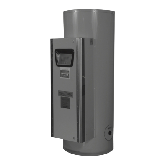
Page 6: Features And Components
features and coMponents Below is an illustration of the water heater with its features called out. The text of this manual will refer to the items shown. uIM - user Interface Module (on front of hinged access door) fIGure 1. -
Page 7: Approvals
approVals All models are listed by Underwriters Laboratories Inc. asMe Model and ratInG locatInG the new water heater facts to consIder aBout the locatIon Near a floor drain. The heater should be located in an area where leakage of the tank or connections will not result in damage to the area adjacent to the heater or to lower floors of the structure. -
Page 8: Installation
InstallatIon requIred aBIlIty Installation and service of this water heater requires ability equivalent to that of a qualified agency (page 2) in the field involved. Plumbing and electrical work is required. General The installation must conform with these instructions and the local code authority having jurisdiction and the requirements of the power contaMInated water company. -
Page 9: Water Line Connections
For safe operation of the water heater, the temperature and pressure number listed on the back cover of this manual for technical relief valve must not be removed from its designated opening nor assistance. plugged. The temperature-pressure relief valve must be installed directly into the fitting of the water heater designed for the relief valve. -
Page 10: Electrical Data
electrIcal data General control cIrcuIts Check the water heater model and rating plate information against The water heater is equipped with an electronic control system. The the characteristics of the branch circuit electrical supply. Do not system includes a CCB (Central Control Board) circuit board, an connect the heater to an improper source of electricity. - Page 11 taBle 1. Allowable Ampacities of Insulated Conductors Not More Than Three Conductors in Raceway or Cable or Earth (Directly Buried), Based on Ambient Temperature of 30°C (86°F) Size Temperature Rating of Conductor Size 60°C 75°C 85°C 90°C 60°C 75°C 85°C 90°C (140°F) (167°F)
-
Page 12: Wiring Diagrams
wIrInG dIaGraMs wIrInG dIaGraMs dIaGraM 1. sMall coMMercIal wIre dIaGraM 208-240V / 3ph dIaGraM 2. sMall coMMercIal wIre dIaGraM 208-240V / 3-1ph... - Page 13 3-1 phase conVersIons In the case where the unit is phase convertible and it has only one contactor, jumper wires (provided) must be added according to the phase of the supply voltage. See the diagram below. For single-phase connection, jumpers A-C and B-D must be added. For three- phase connection, jumper B-C must be added.
- Page 14 dIaGraM 4. sMall coMMercIal wIre dIaGraM 300-600V / 3ph dIaGraM 5. sMall coMMercIal electrIc 300-600V 3ph, linear or progressive...
-
Page 15: Operation
operatIon General Close the cabinet door and perform start up checks listed below before turning on the electricity. Refer to the Features and Components section of this manual for the InItIal start up location of components mentioned in the instructions that follow. neVer operate the heating elements without being certain the water The following checks should be made by the installer when the water heater is filled with water, and a temperature and pressure relief valve... -
Page 16: Temperature Regulation
teMperature reGulatIon hIGh teMperature lIMIt controls (eco) teMperature adjustMent This water heater is equipped with an ECO (energy cut off) non adjustable high temperature limit control. An ECO is a normally closed switch that opens (activates) on a rise in temperature. If the ECO switch contacts open (activate) due to abnormally high water temperatures the control system will lock-out and disable further heating element operation. -
Page 17: Control System Operation
control systeM operatIon heatInG eleMent operatIon control systeM features advanced diagnostics Plain English text and animated icons display detailed operational and diagnostic information. LCD screen on the front of the water heater displays the Sequence of Operation in real time. Fault or Alert messages are displayed when operational problems occur. - Page 18 Status: The Operating State of the control system is displayed Help: The right Operational Button is pressed to access instructions beneath the Operating Set Point. and explanations for user settings, Operating States, Status Icons, manufacturer’s web address, technical support phone number and service agent contact information.
- Page 19 taBle 4 - operatInG states state descrIptIon The water heater is not in an active heating cycle. This usually indicates the temperature in the tank has reached the Standby Operating Set Point and the control system has terminated the heating cycle. Heating The control system is in the Heating Mode.
-
Page 20: Temperatures Menu
teMperatures Menu operating sequence On a water heater equipped with 3 heating elements, with an operating set point Operating Set Point of 120°F and all Differential settings at 2°F the On/Off sequencing of heating elements would be as follows: User adjustable setting 90°F to 190°F range; factory default is 120°F. - Page 21 temperature settings The Operating Set Point and the Differential Settings are adjusted in the Temperatures Menu. The following instructions explain how to adjust these user settings and navigate the control system menus. actIon dIsplay From the Desktop Screen, press the Operational Button underneath “MENU”...
-
Page 22: Heater Status Menu
heater status Menu element # on Displays the on/off status of each heating element. Yes = On, No = This menu displays non adjustable operational information. Use the Off. Up & Down Buttons to navigate to the bottom of this menu. tank full top of Menu Displays the status of the optional LWCO (Low Water Cut Off) device. - Page 23 The Economy Set Point is the water temperature the control daily operating Mode (sun - Mon - tue - wed - thu - fri - sat) system maintains during programmed Economy Mode time periods. “Economy Set Point” is displayed instead of Seven daily sub menus are listed at the bottom of the Economy “Operating Set Point”...
-
Page 24: Economy Mode Settings
econoMy Mode settInGs setpoint adjustment Value actIon dIsplay From the Desktop screen, press the Operational Button underneath “MENU” to enter the Main Menu. Notice how the text above the Operational Buttons on the display changes as you navigate through the various menus and screens. Use the Up/Down buttons to select (highlight in black) the Economy Mode Setup menu from the Main Menu. - Page 25 econoMy Mode settInGs time clock settings actIon dIsplay From the Desktop Screen navigate to the Economy Mode Setup menu. Use the Up/Down buttons to select (highlight in black) Current Time sub menu. Press the Operational Button underneath “CHANGE” to enter the Current Time sub menu.
- Page 26 econoMy Mode settInGs daily operating Mode settings ACTION DISPLAY economy Mode all day: From the Economy Mode Setup menu use the Up/Down buttons to select (highlight in black) the Daily sub menu for “Sun.” Press the Operational Button underneath “CHANGE” to enter this menu. Use the Up/Down buttons to select (highlight in black) the “Economy Mode All Day”...
-
Page 27: Alarm Output Setup Menu
alarM output setup Menu alarm output settings Changing the user settings in this menu is done using the same Permits user to set the condition (from a list of options) for when methods for changing the Operating Set Point. the CCB’s integral alarm output relay will be energized. Alarm relay connections (common, normally open, normally closed) are located on Service Note: Adjustable user settings in the Alarm Output Setup the J3 terminal strip on the CCB - see wiring diagrams. -
Page 28: Current Fault/Alert Menu
Bottom of Menu messages in chronological order in this menu. The most recent will be at the top of the list. A time stamp is displayed below each listed Fault and Alert message showing when the Fault or Alert condition occurred. The Fault History is useful when dealing with intermittent operational problems or when the customer has reset the control system prior to a service agent’s arrival. -
Page 29: Restore Factory Defaults Menu
restore factory defaults Menu This control system menu allows the user to restore most of the control system’s user settings to their factory default settings. user settings in the alarm output setup and display settings menus are unaffected by executing restore factory defaults. -
Page 30: Maintenance
MaIntenance General If after manually operating the valve, it fails to completely reset and continues to release water, immediately close the cold water inlet to the water heater, follow the draining instructions in the Start Up Water heater maintenance includes inspection and testing of the section of this manual, and replace the temperature-pressure relief Temperature Pressure Relief Valve, periodic tank flushing and valve with a properly rated/sized new one. - Page 31 Characteristics of water supply. and allow scale to dissolve. Do not permit delimer or water to contact heating element electrical terminals. Regardless of water treatment, the elements should be examined regularly. • Silicates, sulfates, and aluminates must be removed by scraping or other mechanical means. Lime scale Lime scale accumulations may cause noises to occur during dissolvents will not remove these types of scale which are operation.
-
Page 32: Troubleshooting Checklist
trouBleshootInG checklIst Before calling for service, check the following points to see if the cause water Is too hot of trouble can be identified and corrected. Reviewing this checklist may eliminate the need of a service call and quickly restore hot water service. Refer to the TEMPERATURE REGULATION section of this manual. -
Page 33: Piping Diagrams
pIpInG dIaGraMs one or two teMperature - one heater *pIpe to open draIn. Install In accordance wIth all local codes. one or two teMperature - two heater... - Page 34 one or two teMperature - three heaters *pIpe to open draIn. Install In accordance wIth all local codes. one or two teMperature - four heaters...
- Page 35 MedIuM teMperature - one heater VertIcal storaGe tank *pIpe relIef ValVe to open draIn. †tank teMperature control set at desIred teMperature (MaX. 170°). heater therMostat set at least 5° hIGher. Install In accordance wIth all local codes. MedIuM teMperature - one heater VertIcal storaGe tank...
- Page 36 MedIuM teMperature - two heaters VertIcal storaGe tank MedIuM teMperature - two heaters horIZontal storaGe tank return lIne froM fIXture cIrculatInG loop (If used) should connect to any openInG near BottoM of tank. *pIpe relIef ValVe to open draIn. †tank teMperature control at desIred teMperature (MaX.
- Page 37 MedIuM teMperature - three heaters VertIcal storaGe tank MedIuM teMperature - three heaters horIZontal storaGe tank *pIpe relIef ValVe to open draIn. †tank teMperature control set at desIred teMperature (MaX. 170°). heater therMostat set at least 5° hIGher. Install In accordance wIth all local codes.
- Page 38 MedIuM teMperature - four heaters VertIcal storaGe tank MedIuM teMperature - four heaters horIZontal storaGe tank *pIpe relIef ValVe to open draIn. †tank teMperature control set at desIred teMperature (MaX. 170°). heater therMostat set at least 5° hIGher. Install In accordance wIth all local codes.
-
Page 39: Warranty
warranty A. O. Smith, the warrantor, extends the following LIMITED WARRANTY to the owner of this water heater: 1. THE TANK If the glass-lined tank in this water heater shall prove upon examination by the warrantor to have leaked due to natural corrosion from potable water therein, during the first THREE years after initial installation, the warrantor will supply a complete new A. - Page 40 A DIVISION OF A. O. SMITH CORPORATION RENTON, WASHINGTON Technical Support: 800 527-1953 Parts Department: 800 433-2515 www.hotwater.com...
Need help?
Do you have a question about the DSE-5 and is the answer not in the manual?
Questions and answers