Advertisement
Quick Links
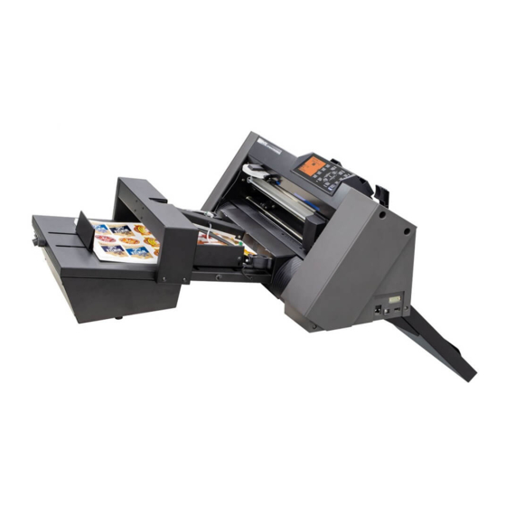
Auto Sheet Feeder
Setup manual
User manual
Read this manual carefully before using the machine,
keep the manual in a handy place for future reference
index
1
Safety precautions
2
Main specifications
3
Dimensions
6
Accessory box
7
Cable connection
8
Overview and adjustings
9
iMark digital cutting software
10
F-Mark feeder position and push roller alignment
11
Cut the first test sheet
13
Print and cut alignment
15
Suction cups and insertion flap replacement.
16
Optical camera mounting
18
Troubleshooting
Advertisement

Subscribe to Our Youtube Channel
Related Manuals for GRAPHTEC F-Mark


Summary of Contents for GRAPHTEC F-Mark
- Page 1 Setup manual Accessory box Cable connection Overview and adjustings User manual iMark digital cutting software F-Mark feeder position and push roller alignment Cut the first test sheet Print and cut alignment Suction cups and insertion flap replacement. Optical camera mounting Troubleshooting...
-
Page 2: Safety Precautions
Always use the recommended AC adapter (EA10682U-120) for the When placing the F-Mark device, allow enough table space, take in ddCutter feeder to prevent any damage or failure. consideration the vibrations generated during operations. -
Page 3: Main Specifications
Main specifications SRA3, A3Extended) ( A3 The F-Mark automatic feeder is part of the CE6000plus ASF Width : 279 ~ 350mm ~ ( 300 350mm with CE6000-60) system. Length : 210 ~500mm up to 700mm with optional extender Media size... - Page 4 Dimensions 43 cm 59 cm 22 cm 120 cm Choose a location that allows an easy access to the adjusting knobs. 82 cm 42 cm 38 cm...
- Page 5 The system can be configured with a plotter different for size and maximum cutting area: The tabletop length to accomodate the system is 82cm, the width varies: CE6000plus-40 with a plotter width of 70cm CE6000plus-60 with a plotter width of 90cm Allow 5cm of clearance on the right and left side to accomodate the power cord an the USB cable.
- Page 6 Peel the adhesive tape on the back Press it firmly un the tabletop Put the plotter on top of the exit tray of the exit tray. The adhesive tape fix the exit tray for a short time, it may drop if you do not place the plotter on top.
-
Page 7: Accessory Box Contents
Accessory box contents Among the items on the accessory box the USB Hub is not normally necessary it is used for troubleshooting in case of bad communicatrion betwern the computer and the system. It may happen in case of overloaded usd port on th computer. You have to connect the power cord to the power adapter and the USB Hub with the miniUSB cable 1.8m long USB cable 1.0m... - Page 8 For the CE6000-40 you can use the cable into the F-Mark accessory box. for the CE6000-60 you have to use the USB cable from the plotter box.
- Page 9 Overview and adjustings On the F-Mark there some knobs that allow some adjustment Insertion Flap depending on the paper size and type. The side paper guide knob adjusts the opening of the side giudes accordingly to the media width. Keep the side guide loose on the media borders.
- Page 10 The system is connected to the computer through a USB port. Installation of the Graphtec driver DO NOT INSTALL THE GRAPHTEC DRIVER ! You only have to install the driver if you want to install the other software supplied with the plotter.
- Page 11 F-Mark feeder position and push roller alignment When you launch the software you can see two preview The feeder can slide left and right accordingly to the paper rectangular area on the top part ow the window. width. On the plotter there is a label with the indication Thel left one is a live preview of the camera view, the left where to align the left edge of the feeder for each paper size.
- Page 12 When you turn on the F-Mark feeder, it performs an initialization cycle. The arms moves up and down once until it stops in stand by position. A red light appears on the switch button.
- Page 13 Note that the blade holder has two different position, one for kiss cutting of adhesive sheets and the other for die cutting on cardboard. The calibration process has to be operated ALWAYS with the blade on the adhesive cutting position. The software arrange the correct position when using die cutting on the other position.
- Page 14 Print and cut alignment adjustment next to the preview allows you to set the vertical position of the cut path. By increasing the Y you move the cutting upwards. in this case the cut line is 0.5mm too low By decreasing the Y you move the cutting downwards. set 5 on the Y value to move it higher.
- Page 15 Press the ‘Calibration’ button Press the ‘Calibration’ button When you press ‘Cut Marker’ When you press ‘Cut Marker’ the plotter cuts a small square. the plotter cuts a small square. Remove the small square adhesive to expose the white liner Remove the small square adhesive to expose the white liner Press the ‘Read Marker’...
- Page 16 Suction cups and insertion flap replacement There are two spare suction cups available into the accessory box. You have to replace them when you notice some difficulties on picking up the sheet. Upon a normal use of the feeder you have to replace them once a year.
- Page 17 Optical camera mounting Remove the camera and accessories from the bag. The camera is composed of two parts that you have to separate before mounting. Remove completely the right screw as in the picture. Release the left screw until the lower bracket is released, leave the left screw in place there is a plastic ring tha hold it.
- Page 18 Align the camera with the bracket, you can use the hole where the screw have been removed fo the alignment. If you insert a white sheet on the plotter it may help to see trough the hole. Press firmly until the metal parts are in contact. Fix the two screws tight.
-
Page 19: Troubleshooting
Troubleshooting 1 - The feeder does not moves turning it on The feeder does not execute the initialization cycle, the arm does not move when you turn on the switch. Check if the green light on the switch is on. Check the connection of the power supply to the feeder. - Page 20 3 - Feeder off or not connected When you press ‘Cut Test’ or ‘Start’ from the software you get the following error message: Turn on the feeder and repeat the command from the software. The power switch in ON and you receive the same error message: If the arm moves and executes the initialization cycle.
Need help?
Do you have a question about the F-Mark and is the answer not in the manual?
Questions and answers