
Subscribe to Our Youtube Channel
Related Manuals for System Sensor Fire-Lite Alarms MRP-4424


Summary of Contents for System Sensor Fire-Lite Alarms MRP-4424
- Page 1 PN 15180:F0 ECN 00-543 Agent Release Control Panel MRP-4424 Instruction Manual Document 15180 03/22/2001 Rev:...
- Page 2 While a fire alarm system may lower insurance Fire Alarm System Limitations rates, it is not a substitute for fire insurance! An automatic fire alarm system–typically made up of smoke Heat detectors do not sense particles of combustion and detectors, heat detectors, manual pull stations, audible warn- alarm only when heat on their sensors increases at a prede- ing devices, and a fire alarm control with remote notification termined rate or reaches a predetermined level.
- Page 3 Installation Precautions Adherence to the following will aid in problem-free installation with long-term reliability: WARNING - Several different sources of power can be con- Like all solid state electronic devices, this system may nected to the fire alarm control panel. Disconnect all sources operate erratically or can be damaged when subjected to light- of power before servicing.
-
Page 4: Nfpa Standards
NFPA Standards NFPA Standards This control panel complies with the following NFPA standards: • NFPA 12 - CO2 Extinguishing Systems (High Pressure Only) • NFPA 12A - Halon 1301 Extinguishing Systems • NFPA 12B - Halon 1211 Extinguishing Systems • NFPA 72 - Central Station Signaling Systems (Automatic, Manual, and Waterflow) - Protected Premises Unit Requires NOTI-FIRE 911AC DACT or 411UDAC Universal Digital Alarm Communicator •... -
Page 5: Table Of Contents
Table of Contents Table of Contents NFPA Standards......................4 NFPA Standards ....................4 Underwriters Laboratories Documents ..............4 Other........................4 1. Product Description Overview ........................7 Features ........................7 Options ........................7 Circuits ......................... 8 Input Circuits......................8 Output circuits......................8 Front Panel Control Switches ................ - Page 6 Table of Contents Transmitter Module - 4XTMF ..............27 Zone Relay Module - 4XZMF ..............28 LED Interface Module - 4XLMF..............29 Setting Mode of Operation ..................30 DIP Switch Functions................... 30 Switch #1 - Cross Zone ................. 30 Switch #2 - Supervisory/Releasing Service ..........31 Switch #3 and #4 - Timer Delay ..............
-
Page 7: Product Description
1. Product Description Overview The Fire•Lite MRP-4424 Agent Release Control Panel has been designed as a control center for use in automatic fire supression systems. The panel is a feature-packed control unit suitable to perform detection and control functions associated with the release of gaseous agent/special hazard fire protection systems. The MRP-4424 is designed for maximum reliability with 100% solid state circuitry and isolated relay contacts for outside interfacing and features programmable options to allow on-site customization of the unit for various operating configurations. -
Page 8: Circuits
1. Product Description Circuits Circuits Input Circuits Detector Zone 1 (Style B/D) Detector Zone 2 (Style B/D) Abort (Style B/D) Manual Release (Style B/D) Note: Optional auxiliary relay module 4XZMF tracks these four circuits. Output circuits Notification Appliance Circuit 1 (Style Y/Z) Notification Appliance Circuit 2 (Style Y/Z) Releasing Circuit 1 (Style Y) Releasing Circuit 2 (Style Y) / Supervisory Input (StyleB) -
Page 9: Control Panel
Control Panel 1. Product Description Control Panel Relays Notification Appliance Circuits Alarm Contacts Style Z (Class A) / Style Y (Class B) Trouble Contacts Releasing Circuits Style Y (Class B) 24VDC #1 - Initiating Device Circuit Regulated Nonresettable #2 - Initiating Device Circuit Regulated Resettable #3 - Abort Switch RMS-Regulated... -
Page 10: Dip Switch Functions
1. Product Description DIP Switch Functions DIP Switch Functions The table below describes the DIP switch functions. For a more detailed explaination see "Setting Mode of Operation" on page 30. Cross Zone Determines how NACs and Releasing Circuits respond to an alarm. Supervisory Selects Releasing Circuit #2 to function as a Supervisory Circuit. -
Page 11: Zone Relay Module - 4Xzmf
Options 1. Product Description Zone Relay Module - 4XZMF T B 1 The Zone Relay module provides Form-C contacts for the following: • Relay #1 - Alarm Detected / First Alarm • Relay #2 - Alarm Detected / Second Alarm •... - Page 12 1. Product Description Options Meter Module (Volts-Amps) - 4XMMF The Meter Module provides a voltmeter to measure the voltage across the batteries and an ammeter to measure the charging current to the batteries. The D C V OLT S meters are provided as an assembly that mounts to the lower left-hand corner of the cabinet.
-
Page 13: Specifications
Specifications 1. Product Description Specifications AC Power MRP-4424: 110/120 VAC, 50/60 Hz, 1.2 amps MRP-4424E: 220/240 VAC, 50/60 Hz, 0.6 amps Wire size: minimum #14 AWG with 600V insulation Battery (lead acid only) Maximum Charging Circuit: 27.6V, 1.5 amps Maximum Battery Capacity: 18 AH. Note: Batteries larger than 12 AH require Fire•Lite BB-17F or other UL-listed external battery cabinet. - Page 14 1. Product Description Specifications Notes MRP-4424 Instruction Manual PN 15180:F0 03/22/01...
-
Page 15: Installation
2. Installation Cabinet Mounting Carefully unpack the system and check for shipping damage. Select a suitable location in a clean, dry, vibration-free environment that is not subject to extreme temperatures. Locate the top of the cabinet approximately five feet above the floor with the hinge on the left. -
Page 16: Reinstallation Of Circuit Board
2. Installation Cabinet Mounting The figure below shows the exterior dimensions and mounting hole locations for the cabinet backbox and dimensions of the optional trim ring: 5 .3 75 ” 1 4.62 5 ” (1 3.65 cm ) (3 7.15 cm ) 1 6.12 5 ”... -
Page 17: Installing Optional Voltmeter/Ammeter
Installing Optional Voltmeter/Ammeter 2. Installation Installing Optional Voltmeter/Ammeter To monitor battery voltage and battery charging current, a 4XMMF Meter Module is required. To install the power meter module follow the steps below: Step Action Cut the jumper wire labeled “AMP”. Secure the module to the backbox with the hardware provided. -
Page 18: Power Connections
2. Installation Power Connections Power Connections WARNING: Do not apply any type power to this control panel until all connections have been made and verified. AC Connections Disconnect (open) the circuit breaker in the AC main breaker panel and tag it “Out of Service”. Note: Refer to "Power-Up Procedure"... -
Page 19: Power-Limited Wiring Requirements
Power-limited Wiring Requirements 2. Installation Observe polarity when connecting the batteries. Connect the battery cable (p/n 75203 or 75202, depending on terminal size of battery) to terminal J9 on the main circuit board using the plug-in connector provided. Connect red wire to positive (+) terminal and black wire to negative (–) terminal on opposing batteries. Do NOT connect battery interconnect wire at this time. -
Page 20: Initiating Device Circuits
2. Installation Initiating Device Circuits Initiating Device Circuits The control panel provides two Initiating Device Circuits (#1 and #2) and they may be configured as either Style D (Class A) or Style B (Class B). Circuit #3 is designated as an Abort Switch Circuit and Circuit #4 is a Manual Release Circuit. -
Page 21: Four-Wire Smoke Detector Connections
Initiating Device Circuits 2. Installation Four-Wire Smoke Detector Connections A maximum of 200mA is available from the 24VDC Resettable Power circuit on TB1 (+24VR terminals). Any power that is drawn from the 24VDC Nonresettable Power on TB2 (+24VNR terminal) must be subtracted from available resettable power. -
Page 22: Output Circuits
2. Installation Output Circuits Output Circuits Notification Appliance Circuits The control panel provides two Style Z (Class A) or Style Y (Class B) Notification Appliance Circuits, which are supervised and power-limited. Each circuit is capable of 1.5 amps of current. Total current drawn from both NACs and both Releasing Circuits (see "Releasing Circuits"... -
Page 23: Releasing Circuits
Output Circuits 2. Installation Releasing Circuits CAUTION: To prevent accidential discharge, connect releasing devices after initial panel tests are completed. The control panel provides two Style Y (Class B) Releasing Circuits, which are nonpower-limited. Circuit #2 can be configured for a Supervisory Circuit (see "Setting Mode of Operation" on page 30) and will then be power-limited. -
Page 24: Alarm Relay Circuit
2. Installation Powering External Devices Alarm Relay Circuit One Form-C dry contact alarm relay is provided in the basic panel for controlling supplementary devices. Contacts are rated 2 amps at 30 VDC and 0.5 amps at 30 VAC (resistive) and are non-silenceable when an alarm occurs. -
Page 25: Optional Modules
Optional Modules 2. Installation Optional Modules Overview The control panel has two module connectors - J5 (upper position) and J8 (lower position). Three modules are available for the panel and they can be used in any combination, including duplicate modules. The corresponding option jumper must be cut before installation of an optional module, to enable module supervision. -
Page 26: Installation - Lower Position
2. Installation Optional Modules Installation - Lower Position To install either the 4XTMF, 4XZMF or 4XLM module in the lower position follow these instructions: Step Action Cut jumper ‘OPT2’ on main circuit board. Remove the lower-right screw securing the main board to the lower rail. Replace with a stand-off and tighten securely. -
Page 27: Setup And Configuration
Optional Modules 2. Installation Setup and Configuration Transmitter Module - 4XTMF Connect a Remote Alarm circuit, Remote Trouble circuit or a Municipal Box to the Transmitter Module as shown below. Polarities shown in activated positions. Note: Dummy load terminals 6 and 7 (4.7K, 1/4 W resistor) if Municipal Box is not connected. Note: Remote Alarm, Remote Trouble and Municipal Box wiring can leave the building. -
Page 28: Zone Relay Module - 4Xzmf
2. Installation Optional Modules Zone Relay Module - 4XZMF Relay #1 through #4 on this module have specific functions based on the configuration of DIP switches #1 and #2 on the control panel. See “Zone Relay Module Configuration” on page 32 for a more detailed explaination of the conditions that will activate each relay under the different DIP switch setings. -
Page 29: Led Interface Module - 4Xlmf
Optional Modules 2. Installation LED Interface Module - 4XLMF Connect the terminals on TB1 of the LED Interface Module to the corresponding terminals of the RZA- 4XF Remote Annunciator. Make wiring connections with system power off. Maximum wire impedance is 50 ohm per wiring connection. The wiring of this module must follow the requirements as specified under "Power-limited Wiring Requirements"... -
Page 30: Setting Mode Of Operation
2. Installation Setting Mode of Operation Setting Mode of Operation Select operating mode by setting the SW1 DIP switches as described below; basic programming options are shown in this section. After any changes are made to the configuration of the switches, the panel must be reset. For Canadian use, refer to "Sprinkler Supervisory Tracking"... -
Page 31: Switch #2 - Supervisory/Releasing Service
Setting Mode of Operation 2. Installation Switch #2 - Supervisory/Releasing Service Set the function of Releasing Circuit #2 by setting this switch. REL #2 Will function as a solenoid releasing REL #2 Will function as a supervisory input circuit. circuit. •... -
Page 32: Zone Relay Module Configuration
2. Installation Setting Mode of Operation Zone Relay Module Configuration Relay #1, #2, #3 and #4 of the the 4XZMF Zone Relay Module have specific functions based on the configuration of DIP Switches #1 and #2 on the control panel. The table below provides a description of these functions. -
Page 33: Power-Up Procedure
Power-Up Procedure 2. Installation Power-Up Procedure WARNING: Prior to energizing this panel, notify all personnel and authorities, including any personnel who may be working on, around, or near this unit. WARNING: Battery contains sulfuric acid which can cause severe burns to the skin and eyes and can destroy fabrics. - Page 34 2. Installation Power-Up Procedure Notes MRP-4424 Instruction Manual PN 15180:F0 03/22/01...
-
Page 35: System Operation
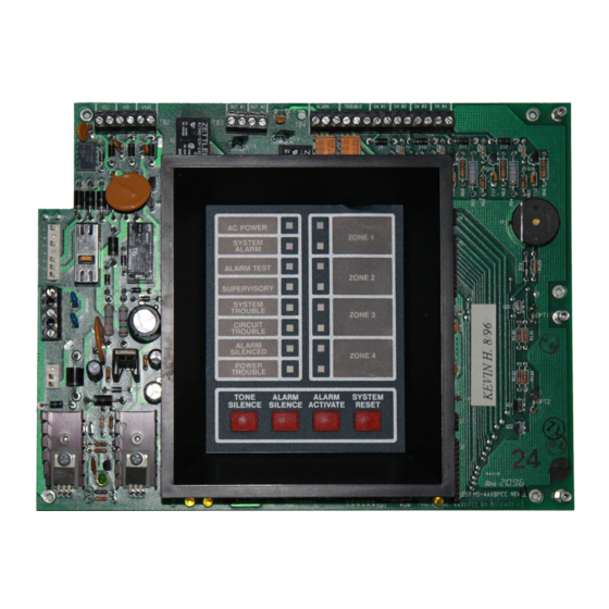
3. System Operation WARNING: When used for CO releasing applications, observe proper precautions as stated in NAFP 12. Do not enter the protected space unless physical lockout and other safety procedures are fully completed. Do not use software disable functions in the panel as lockout. System Status LEDs Alarm, Trouble and Supervisory LEDs will flash on and off until the event(s) has been acknowledged (TONE or ALARM SILENCE), at which point the LED will illuminate steadily. -
Page 36: Control Switches
3. System Operation Control Switches Control Switches T O N E A L A R M A L A R M S Y S T E M S IL E N C E S IL E N C E A C T IVAT E R E S E T Figure 22 Control Panel Switches Tone Silence - Pressing this switch acknowledges alarms, troubles and supervisories. -
Page 37: Piezo
Piezo 3. System Operation Piezo The piezo (local buzzer) generates different tone patterns for different event conditions: • Alarm - Generates a steady tone, no pulse. • Trouble - Pulses one second on, one second off. Repeats 30 pulses per minute. •... -
Page 38: Last Event Recall
3. System Operation Last Event Recall Last Event Recall Last Event Recall allows the user to display the previous panel status. The Last Event Recall makes use of the four panel switches as follows: Press and hold in the TONE SILENCE switch. With the TONE SILENCE switch held in, press (in sequence) the SYSTEM RESET switch, the ALARM ACTIVATE switch, and then the ALARM SILENCE switch. -
Page 39: Single Zone In Alarm (Cross-Zone) Condition
System Events 3. System Operation Single Zone in Alarm (Cross Zone) Condition Upon actuation of a single-zone initiating device, a red alarm LED will illuminate to indicate whether Zone 1 or Zone 2 is in alarm. In addition to the LED, a single-zone alarm will activate the Alarm Relay; the piezo and remote NAC #1 will start sounding. - Page 40 3. System Operation System Events Notes MRP-4424 Instruction Manual PN 15180:F0 03/22/01...
-
Page 41: Appendix A: Secondary Power Calculations
Appendix A: Secondary Power Calculations Standby Battery Requirements The Standby Battery Current obtained in the table below represents the amount of current that must be supplied by the secondary power source (batteries) to sustain control panel operation for one hour. Note: The control panel will support the installation of one or two optional modules, including two of the same type of module. -
Page 42: Calculating The Battery Capacity
Appendix A: Secondary Power Calculations Calculating the Battery Capacity Calculating the Battery Capacity Use this table to determine the battery capacity required by the system. Standby Battery Current Required Standby Time in Hours (from Table 1) Standby (typically 24 , 60 , or 90 hours) ] amps... -
Page 43: Appendix B: Nfpa Standard-Specific Requirements
Appendix B: NFPA Standard-Specific Requirements Minimum System Requirements The control panel has been designed for use in commercial, industrial, and institutional applications and meets the requirements for service under the National Fire Protection Association (NFPA) Standards outlined in this appendix. The minimum system components required for compliance with the appropriate NFPA standard are listed below. -
Page 44: Digital Alarm Communicator/Transmitter - Noti-Fire 911Ac
Appendix B: NFPA Standard-Specific Requirements Digital Alarm Communicator/Transmitter - Noti-Fire 911AC Digital Alarm Communicator/Transmitter - Noti-Fire 911AC Note: This application is not FM approved Using the Noti-Fire 911AC DACT for connection to a Central Station Receiver or Protected Premises Receiving Unit. •... -
Page 45: Universal Digital Alarm Communicator - 411Udac
Universal Digital Alarm Communicator - 411UDAC Appendix B: NFPA Standard-Specific Requirements Universal Digital Alarm Communicator - 411UDAC The following figure illustrates an example of Central Station/Remote Station Receiver or Protected Premises Receiving Unit reporting using a 411UDAC. The relay contacts of the MRP-4424 may be used to trip any dialer listed for Central Station/Remote Station services. -
Page 46: Local Energy Municipal Box
Appendix B: NFPA Standard-Specific Requirements Local Energy Municipal Box Local Energy Municipal Box Using the 4XTMF Transmitter Module for connection to a Local Energy Municipal Box. • The Municipal Box circuit supervises for ground faults and opens (i.e. missing wire) but not for direct short between two wires. -
Page 47: Remote Station Receiver - Rs82-9
Remote Station Receiver - RS82-9 Appendix B: NFPA Standard-Specific Requirements Remote Station Receiver - RS82-9 Using the 4XTMF Transmitter Module for connection to a Fire•Lite RS82-9 Remote Station Receiver. • Intended for connection to a polarity reversal circuit of a remote station receiving unit having compatible ratings. -
Page 48: Potter Eft-C Mcculloh Transmitter
Appendix B: NFPA Standard-Specific Requirements Potter EFT-C McCulloh Transmitter Potter EFT-C McCulloh Transmitter Note: This application is not FM approved. • Connections between control panel and the transmitter are supervised by the transmitter. • Use transformer model ULT STK. NO. 1000391 (listed, Class 2, 12 V, 10 VA.). See Potter Electric Signal Company Bulletin # 748. -
Page 49: Appendix C: Testing & Maintenance
Appendix C: Testing & Maintenance Testing Inspection Perform the following prior to applying power to the system. • Check the actual wiring hookup with the wiring diagrams. • Insure that no pieces of wire have fallen into the circuitry. • Check for missing or damaged parts. Alarm Test An initial alarm test should be conducted following installation to determine that all parts of the system are functioning properly. - Page 50 Appendix C: Testing & Maintenance Troubleshooting Table 3 Troubleshooting Table Symptom Problem Solution 1. Check TB2 for proper connections. 2. Remove all field wiring and install dummy ELR at output circuit. Check for supervisory voltage across it, (Normal -2.3 V), if problem persists, replace circuit Circuit trouble Notification appliance circuit board.
- Page 51 Index Index Numerics circuit breaker CO2 releasing applications 110/120 VAC conductors 220/240 VAC 15, 45 conduit 43, 45 411UDAC configuration, Zone Relay Module 11, 25 4XLMF LED Interface Module 30, 39 Cross Zone 12, 17 4XMMF Meter Module 13, 23 current 10, 25, 43, 46, 47 4XTMF Transmitter Module...
- Page 52 Index Maximum Battery Capacity Maximum Charging Circuit 32, 48 General Alarm maximum resistance 35, 46 ground fault 12, 17 Meter Module microprocessor minimum clearance Indicating Circuit #1 minimum voltage initial alarm test module connectors initiating circuits motherboard 39, 43 initiating device mounting hole locations Initiating Device Circuit mounting holes...
- Page 53 Index programmed Supervisory/Releasing Service 43, 44, 45 Protected Premises Receiving Unit supplementary devices protected space suppresant agent switch, disable System Alarm Relay System Trouble rail System Trouble LED 15, 16 rail, backbox red wire regulated power relay contacts tag, “Out of Service” 25, 26 Relay, System Alarm terminal identification label...
- Page 54 MRP-4424 Instruction Manual PN 15180:F0 03/22/01...
- Page 55 Limited Warranty The manufacturer warrants its products to be free from defects in materials and workmanship for eighteen (18) months from the date of manufacture, under normal use and service. Products are date-stamped at time of manufacture. The sole and exclusive obligation of the manufacturer is to repair or replace, at its option, free of charge for parts and labor, any part which is defective in materials or workmanship under normal use and service.
- Page 56 World Headquarters One Fire-Lite Place, Northford, CT 06472-1653 USA 203-484-7161 • Fax 203-484-7118 www.firelite.com...
Need help?
Do you have a question about the Fire-Lite Alarms MRP-4424 and is the answer not in the manual?
Questions and answers