Advertisement
Quick Links
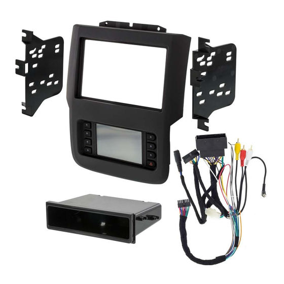
INSTALLATION INSTRUCTIONS FOR PART 99-6527B
Ram 1500/2500/3500 2013-up
KIT FEATURES
• ISO DIN radio provision with pocket
• ISO DDIN radio provision
• Touchscreen display for climate and personalization features
• Painted black
KIT COMPONENTS
• A) Radio trim panel with touchscreen display • B) Radio brackets • C) Pocket • D) (4) #8 x 3/8" Phillips screws
A
B
WIRING & ANTENNA CONNECTIONS
Wiring Harness: • Axxess interface and harness included Antenna Adapter: • 40-EU55 (sold separately)
METRA – The World's best kits.
(with 8" touchscreen)
99-6527B
C
metraonline.com
®
Dash Disassembly ..............................................2-3
Kit Preparation ....................................................... 4
Kit Assembly
– ISO DIN radio provision with pocket ...................... 5
– ISO DDIN radio provision ...................................... 5
Axxess Interface Installation ...........................6-15
TOOLS REQUIRED
• Panel removal tool • Phillips screwdriver
D
• 9/32" socket wrench • Torx T-20 screwdriver
CAUTION!
and especially air bag indicator lights must be connected before
cycling the ignition. Also, do not remove the factory radio with
the key in the on position, or while the vehicle is running.
Table of Contents
All accessories, switches, climate controls panels,
© COPYRIGHT 2017 METRA ELECTRONICS CORPORATION
Advertisement

Related Manuals for Metra Electronics 99-6527B


Summary of Contents for Metra Electronics 99-6527B
- Page 1 INSTALLATION INSTRUCTIONS FOR PART 99-6527B Table of Contents Ram 1500/2500/3500 2013-up (with 8” touchscreen) Dash Disassembly ..........2-3 99-6527B Kit Preparation ............4 Kit Assembly KIT FEATURES – ISO DIN radio provision with pocket ...... 5 • ISO DIN radio provision with pocket –...
- Page 2 99-6527B Dash Disassembly 1. Remove the rubber tray liner inside 3. For models with a center console: the tray at the top center of the a. Remove the rubber liner from dash, and then remove the (2) Torx the storage tray in front of T-20 screws exposed.
- Page 3 99-6527B Dash Disassembly (cont.) 4. Unsnap and remove the entire center dash panel. (Figure D) 5. Remove the (4) 9/32” screws securing the radio/display screen, and then unplug & remove. (Figure E) Continue to Kit Preparation (Figure D) (Figure E)
- Page 4 (Figure A) 2. Remove the (13) Phillips screws securing the radio/climate control panel, and then remove. (Figure A) 3. Secure the 99-6527B radio trim panel with touchscreen display to the panel using the factory hardware removed in step 2.
- Page 5 99-6527B Kit Assembly ISO DIN radio provision with pocket ISO DDIN radio provision 1. Attach the pocket to the radio 1. Attach the brackets to the radio brackets using the (4) #8 x 3/8” using the screws supplied with Phillips screws provided. (Figure A) the radio.
-
Page 6: Table Of Contents
99-6527B Axxess Interface Installation INTERFACE FEATURES TABLE OF CONTENTS • Provides accessory power (12-volt 10-amp) Connections to be made ................7-9 • Retains R.A.P. (retained accessory power) Installing the interface ................10 • Provides NAV outputs (parking brake, reverse, speed sense) Initializing the interface ................ -
Page 7: Connections To Be Made
99-6527B Connections to be made Attention! This interface will work with models that are either non-amplified, or From the 6527 harness to the aftermarket radio: amplified. Please follow the instructions carefully for your model vehicle. Failure to • Connect the Black wire to the ground wire. - Page 8 99-6527B Connections to be made (cont.) Attention! This interface will work with models that are either non-amplified, or amplified. The following (3) wires are only for multimedia/navigation radios that require these wires. Please follow the instructions carefully for your model vehicle. Failure to do so will result in •...
- Page 9 99-6527B Connections to be made (cont.) 3.5mm jack - steering wheel control retention: • Universal “2 or 3 wire” radio: Connect the steering wheel control wire, referred to as Key-A or SWC-1, to the Brown wire of the connector. Then The 3.5mm jack is to be used to retain audio controls on the steering wheel control.
-
Page 10: Installing The Interface
99-6527B Installing the interface Initializing the interface Attention! If the interface loses power for any reason, the following steps It is highly advisable to read the following steps beforehand, to ensure a clear understanding of what is to be expected. The following steps must be done in the order that they are numbered. -
Page 11: Touchscreen Display Operation
99-6527B Touchscreen display operation Climate Control screen Heated seats screen • This is the climate control screen which will be displayed on the touchscreen display. • This is the Heated/Cooled Seats, Heated Steering, and Mirror Dimming screen which This is considered the Main Menu. - Page 12 99-6527B Touchscreen display operation (cont.) ECO/ESC/PARK-SENSE/SPORT/STOP-START screen • ECO – Fuel Economy Mode • ESC – Electronic Stability Control • PARK-SENSE – ParkSense Rear Park Assist System • SPORT – Sport Mode • STOP-START – Stop/Start System Continued on the next page •...
- Page 13 99-6527B Touchscreen display operation (cont.) Configuration Settings screen • Steering Wheel Controls • Remap Buttons – For remapping the steering wheel control buttons • Dual Assign – For dual assigning the steering wheel control buttons (long button press) • Select Radio – For auto detecting the radio, or changing the radio type •...
-
Page 14: Steering Wheel Control Settings
99-6527B Steering wheel control settings Select Radio screen * Note: If the interface shows an Alpine radio, and you do not have an Alpine radio, that means the interface does not detect a radio connected it, i.e., an open connection. Verify that the 3.5mm jack is connected to the correct steering wheel jack/wire in the radio. - Page 15 99-6527B Steering wheel control settings (cont.) Remap Button screen Dual Assign screen • The interface has the ability to change the button assignment for the steering • The interface has the capability to assign two functions to a single button, wheel control audio buttons, except Volume-Up and Volume-Down.
- Page 16 INSTALLATION INSTRUCTIONS FOR PART 99-6527B IMPORTANT If you are having difficulties with the installation of this product, please call our Tech Support line at 1-800-253-TECH. Before doing so, look over the instructions a second time, and make sure the installation was performed exactly as the instructions are stated.
Need help?
Do you have a question about the 99-6527B and is the answer not in the manual?
Questions and answers