Table of Contents
Advertisement
Quick Links
Intel® Server D50TNP
Family
Intel® Server Board D50TNP Family
Intel® Module D50TNP Family
Intel® Server System D50TNP Family
Integration and Service Guide
A guide providing instructions for the insertion and
extraction of system components and available Intel
accessories and spares.
Rev. 1.0
May 2021
Delivering Breakthrough Data Center System Innovation – Experience What's Inside!
Advertisement
Table of Contents

Subscribe to Our Youtube Channel
Related Manuals for Intel D50TNP


Summary of Contents for Intel D50TNP
- Page 1 Intel® Module D50TNP Family Intel® Server System D50TNP Family Integration and Service Guide A guide providing instructions for the insertion and extraction of system components and available Intel accessories and spares. Rev. 1.0 May 2021 Delivering Breakthrough Data Center System Innovation – Experience What’s Inside!
- Page 2 <This page intentionally left blank>...
- Page 3 Intel® Server D50TNP Family Integration and Service Guide Document Revision History Date Revision Changes May 2021 Initial production release.
- Page 4 You may not use or facilitate the use of this document in connection with any infringement or other legal analysis concerning Intel products described herein. You agree to grant Intel a non-exclusive, royalty-free license to any patent claim thereafter drafted which includes subject matter disclosed herein.
- Page 5 Intel recommends the following steps be taken when performing any procedures described within this document or while performing service to any computer system.
- Page 6 Remove all installed modules from the system before attempting to install the system into the rack. • Due to the weight of a system, Intel recommends carrying the system with two people supporting the system from the sides or using a mechanical lift or a cart when moving the system from one location to another.
- Page 7 Note: This requirement applies only to Intel® server system products released in 2019 or later. Legacy Intel® server system products (released in 2018 or earlier) provide safeguards that require no additional access restrictions.
-
Page 8: Table Of Contents
Intel® Server D50TNP Family Integration and Service Guide Contents 1. Introduction ................................19 Reference Documents and Support Collaterals ....................20 2. L6 Integrated System – Essential System Component Installation .............. 22 Air Duct Removal / Installation ..........................24 2.1.1 Air Duct Removal ................................24 2.1.2... - Page 9 EDSFF Drive Extraction ..............................87 3.10.2 EDSFF Drive Installation .............................. 87 3.11 Intel® Virtual RAID on CPU (Intel® VROC) Upgrade Key Installation ............88 3.12 Trusted Platform Module (TPM) Installation ...................... 88 3.13 Ethernet Management Port Module (EMP Module) (iPC – AXXFCEMP) ..........89 4.
- Page 10 Accelerator Module Riser Card Replacement (iPC – D50TNP2MFALAC Only) ........171 7.13 Accelerator Module Power Connector Board Replacement (iPC – D50TNP2MFALAC Only) ..173 7.14 Intel® Virtual RAID on CPU (Intel® VROC) Upgrade Key Replacement ..........175 7.15 Trusted Power Module (TPM) Replacement ....................175 7.16 Power Supply Replacement............................
- Page 11 Intel® Server D50TNP Family Integration and Service Guide Appendix G. Product Safety – Multi-Language ....................221 Appendix H. Glossary ............................... 233 List of Figures Figure 1. System Directional Reference ............................23 Figure 2. Removing the Air Duct ................................. 24 Figure 3. Installing the Air Duct ................................24 Figure 4.
- Page 12 Intel® Server D50TNP Family Integration and Service Guide Figure 37. Liquid-Cooling Loop Components ..........................45 Figure 38. Removing Front VR Cooling Block’s Protective Covers ..................46 Figure 39. Installing Front VR Blocks ..............................47 Figure 40. Assembling the Manual Applicator ..........................47 Figure 41.
- Page 13 Figure 107. EDSFF Drive Extraction from the Chassis ....................... 87 Figure 108. EDSFF drive Installation into the Chassis ....................... 87 Figure 109. Installing the Intel® VROC Upgrade Key ........................88 Figure 110. Installing the Trusted Platform Module (TPM) ..................... 88 Figure 111.
- Page 14 Figure 129. 2U Storage Module Component Identification ....................102 Figure 130. 2U Accelerator Module Component Identification ..................103 Figure 131. Intel® Server Board D50TNP1SB Feature Identification ................103 Figure 132. Intel® Server Board D50TNP1SBCR Feature Identification ................104 Figure 133. Onboard LED Location ..............................104 Figure 134.
- Page 15 Intel® Server D50TNP Family Integration and Service Guide Figure 162. Processor Carrier Clip Removal from PHM Assembly ..................123 Figure 163. Installing Processor Carrier Clip onto Processor – Part 1 ................123 Figure 164. Installing Processor Carrier Clip onto Processor – Part 2 ................124 Figure 165.
- Page 16 Intel® Server D50TNP Family Integration and Service Guide Figure 204. Installing the M.2 SSD ..............................145 Figure 205. Installing Liquid-Cooled M.2 Cold Plate....................... 146 Figure 206. 1U Riser Assembly and Riser Card Features (D50TNP1MHCPAC and D50TNP2MHSTAC) ... 147 Figure 207. 1U Riser Assembly and Riser Card Features (D50TNP1MHCRAC D50TNP1MHCRLC, and D50TNP1MHEVAC) ..............................
- Page 17 Figure 256. Accelerator Module Power Connector Board Removal ................. 173 Figure 257. Accelerator Module power connector board installation ................174 Figure 258. Removing the Intel® VROC Upgrade Key ......................175 Figure 259. Installing the Intel® VROC Upgrade Key ....................... 175 Figure 260.
- Page 18 Figure 292. Onboard POST Diagnostic LEDs ..........................207 List of Tables Table 1. Intel® Server D50TNP Family Reference Documents and Support Collaterals ..........20 Table 2. Intel® D50TNP Module Family............................22 Table 3. BIOS Setup: Keyboard Command Bar ..........................91 Table 4.
-
Page 19: Introduction
For details on all system and module features, refer to the Intel® Server D50TNP family Technical Product Specification listed in Table 1. Note: In this document, the term Intel® D50TNP Module family refers to all module types supported by the Intel® Server System D50TNP family: Compute Module, Management Module, Storage Module, and Accelerator Module. -
Page 20: Reference Documents And Support Collaterals
Appendix B – General Memory Population Rules. Summary of general memory population rules. Appendix C – System Status LED State Definitions. System status LED operating states and definition. Appendix D – Onboard Configuration and Service Jumpers. Descriptions of jumpers on the D50TNP server board. - Page 21 Product Warranty Information Public 00005886.html Safety and Regulatory Compliance Intel® Server D50TNP Family Technical Product Specification Public Information Note: Intel Confidential documents are made available under a Non-Disclosure Agreement (NDA) with Intel and must be ordered through your local Intel representative.
-
Page 22: L6 Integrated System - Essential System Component Installation
To complete the L6 integration of the D50TNP Intel® Server System to be power-on ready, a chassis from Intel® Server chassis FC2000 family is required to house the L6 integrated modules. The chassis for L6 systems is sold separately and comes with 1600 W or 2100 W power supply units pre-installed. -
Page 23: Figure 1. System Directional Reference
Intel® Server D50TNP Family Integration and Service Guide System Reference In the following procedures, all references to left, right, front, top, and bottom assume the reader is facing the front of the chassis and the front of a module as shown in the following figure (1U air-cooled Compute Module shown). -
Page 24: Air Duct Removal / Installation
Intel® Server D50TNP Family Integration and Service Guide Air Duct Removal / Installation To maintain system thermals for air-cooled modules, the air duct must always be in place when the system is operational. Removal of the air duct is necessary when installing or replacing any system component within the module. -
Page 25: Opening And Closing Storage Module (Ipc - D50Tnp2Mhstac)
2.2 Opening and Closing Storage Module (iPC – D50TNP2MHSTAC) The Intel® D50TNP Storage Module top tray contains the enterprise data center SSD form factor (EDSFF) units while the base of the module contains the processors, memory, and add-in cards. This section provides instructions to open and close the top tray of the storage module. -
Page 26: Closing The Top Tray
2.3 Processor Assembly and Installation The Intel® Server D50TNP family supports 1U height heat sinks and 2U height heat sinks as shown in the following figures. The Compute Module uses 1U height heat sinks. Even though the Storage Module is a 2U height module, it uses the 1U height heat sinks. -
Page 27: Figure 7. 1U Supported Evac Processor Heat Sinks
Intel® Server D50TNP Family Integration and Service Guide The EVAC heat sink is only used in the front for CPU 0. The Compute Module supporting the EVAC heat sink uses the standard back heat sink for CPU 1. Figure 7. 1U Supported EVAC Processor Heat Sinks Figure 8. -
Page 28: Assembly And Installation For Standard Air-Cooled Heat Sinks
Intel® Server D50TNP Family Integration and Service Guide Figure 9. 1U Heat Sinks Installed in Module 2.3.1 Assembly and Installation for Standard Air-Cooled Heat Sinks Components Required: • Gen Intel® Xeon® Scalable processors • Processor carrier clips • 1U processor heat sinks (front and back) or 2U processor heat sinks (front and back) •... -
Page 29: Figure 10. Processor Components And Processor Socket Reference Diagram With Standard Heat Sink
Intel® Server D50TNP Family Integration and Service Guide Figure 10. Processor Components and Processor Socket Reference Diagram with Standard Heat Sink To properly assemble the PHM and install it onto the server board, the procedures described in the following sections must be followed in the order specified. These instructions assume that all the PHM components are new and the Thermal Interface Material (TIM) is already applied to the bottom of the heat sink. -
Page 30: Figure 11. Installing The Processor Carrier Clip Onto The Processor - Part 1
Intel® Server D50TNP Family Integration and Service Guide Figure 11. Installing the Processor Carrier Clip onto the Processor – Part 1 Figure 12. Installing the Processor Carrier Clip onto the Processor – Part 2 1. With the processor still in its tray, place the processor carrier clip over the processor. -
Page 31: Figure 13. Removing The Heat Sink From Its Packaging
5. Locate the processor heat sink. To avoid damage, grasp it by its narrower sides as shown below. Caution: Fin edges of the processor heat sink are very sharp. Intel recommends wearing thin ESD protective gloves when handling the PHM during the following procedures. -
Page 32: Figure 15. Pin 1 Indicator Of Processor Carrier Clip
Intel® Server D50TNP Family Integration and Service Guide Figure 15. Pin 1 Indicator of Processor Carrier Clip 9. Align the pin 1 indicator of processor carrier clip with one of the diagonally cut corners on the base of the heat sink. Or (if present) look for the Pin #1 indicator on the corner of the heat sink label. -
Page 33: Figure 17. Phm Alignment With The Socket Assembly
Intel® Server D50TNP Family Integration and Service Guide Figure 17. PHM Alignment with the Socket Assembly Caution: Processor socket pins are delicate and bend easily. Use extreme care when placing the PHM onto the processor socket. Do not drop it. -
Page 34: Assembly And Installation For Evac Heat Sinks
7. Reinstall the air duct (see Sections 2.1.2). Note: Intel strongly recommends that both processors are installed. If only one processor is installed, do not install a processor heat sink on an empty socket. 2.3.2 Assembly and Installation for EVAC Heat Sinks Components Required: •... -
Page 35: Figure 20. Processor Components And Processor Socket Reference Diagram With Evac Heat Sink
Intel® Server D50TNP Family Integration and Service Guide Figure 20. Processor Components and Processor Socket Reference Diagram with EVAC Heat Sink To properly assemble the PHM and install it onto the server board, the procedures described in the following sections must be followed in the order specified. These instructions assume that all the PHM components are new and the Thermal Interface Material (TIM) is already applied to the bottom of the heat sink. -
Page 36: Figure 21. Installing The Processor Carrier Clip Onto The Processor - Part 1
Intel® Server D50TNP Family Integration and Service Guide Figure 21. Installing the Processor Carrier Clip onto the Processor – Part 1 Figure 22. Installing the Processor Carrier Clip onto the Processor – Part 2 1. With the processor still in its tray, place the processor carrier clip over the processor. -
Page 37: Figure 23. Removing The Heat Sink From Its Packaging
5. Locate the processor heat sink. To avoid damage, grasp it by its narrower sides as shown below. Caution: Fin edges of the processor heat sink are very sharp. Intel recommends wearing thin ESD protective gloves when handling the PHM during the following procedures. -
Page 38: Figure 25. Pin 1 Indicator Of Processor Carrier Clip
Intel® Server D50TNP Family Integration and Service Guide Figure 25. Pin 1 Indicator of Processor Carrier Clip 9. Align the pin 1 indicator of processor carrier clip with one of the diagonally cut corners on the base of the heat sink. Or (if present) look for the Pin #1 indicator on the corner of the heat sink label. -
Page 39: Figure 27. Socket Protective Cover Removal
Intel® Server D50TNP Family Integration and Service Guide 2. If installed, remove the plastic cover from the processor socket. Caution: Do not touch the socket pins. The pins inside the processor socket are extremely sensitive. A damaged processor socket may produce unpredictable system errors. -
Page 40: Figure 28. Phm Alignment With The Socket Assembly
Intel® Server D50TNP Family Integration and Service Guide Figure 28. PHM Alignment with the Socket Assembly Caution: Processor socket pins are delicate and bend easily. Use extreme care when placing the PHM onto the processor socket. Do not drop it. -
Page 41: Figure 30. Tighten Evac Heat Sink Extension
13. With three screws, secure the riser assembly to the module using 8 in-lb. of torque on each screw (see Letter B). 14. Reinstall the air duct (see Sections 2.1.2). Note: Intel requires that both processors are installed. If only one processor is installed, do not install a processor heat sink on an empty socket. -
Page 42: Assembly And Installation For Liquid-Cooled Configurations
Intel® Server D50TNP Family Integration and Service Guide 2.3.3 Assembly and Installation for Liquid-Cooled Configurations Components Required: • Gen Intel® Xeon® Scalable processors • Processor carrier clips • Processor tray as shipped by Intel Required Tools and Supplies: • Anti-static wrist strap and conductive workbench pad (recommended) •... -
Page 43: Figure 33. Installing Processor Carrier Clip Onto Processor - Part 2
Intel® Server D50TNP Family Integration and Service Guide Figure 33. Installing Processor Carrier Clip onto Processor – Part 2 3. Gently press down on two opposite sides at a time of the processor carrier clip until it clicks. Caution: Do not touch the socket pins. The pins inside the processor socket are extremely sensitive. A damaged processor socket may produce unpredictable system errors. -
Page 44: Liquid-Cooling Loop Installation (For Compute Module Ipc - D50Tnp1Mhcrlc)
Liquid-Cooling Loop Installation (for Compute Module iPC – D50TNP1MHCRLC) The liquid-cooled systems within the Intel Server System D50TNP family are designed to operate while being connected to a non-Intel coolant distribution unit that supports Staubli* SCG 06 quick disconnect couplings. The internal cooling is done using a liquid-cooling loop. To maintain system thermals for liquid- cooled modules, the liquid-cooling loop must always be in place when the system is operational. -
Page 45: Figure 37. Liquid-Cooling Loop Components
Phillips* head screwdriver #2 • T-30 Torx* screwdriver • D50TNP Liquid Cooling VR TIMM Application Tools (iPC – TNPLCVRTLS) • D50TNP Liquid Cooling VR TIMM Application Nozzles (iPC – TNPLCVRTNZ) • D50TNP Liquid Cooling VR TIMM Compound (iPC – TNPLCVRCMPD) The liquid-cooling loop package comes with two cooling blocks for the front Voltage Regulator (VR) components on the board. -
Page 46: Figure 38. Removing Front Vr Cooling Block's Protective Covers
Intel® Server D50TNP Family Integration and Service Guide Figure 38. Removing Front VR Cooling Block’s Protective Covers 1. Carefully unpack the front Voltage Regulator (VR) cooling blocks. Remove the protective covers on both ends and ensure the Thermal Interface Material (TIM) is in place and intact. -
Page 47: Figure 39. Installing Front Vr Blocks
Intel® Server D50TNP Family Integration and Service Guide Figure 39. Installing Front VR Blocks 2. Align the front VR cooling blocks to the screw holes following the orientation shown (see Letter A). 3. Using the fastener screws, secure the front VR cooling blocks to the server board (see Letter B). Tighten to 3 in-lb. -
Page 48: Figure 41. Applying Center Vr Thermal Gap Filler
Intel® Server D50TNP Family Integration and Service Guide Figure 41. Applying Center VR Thermal Gap Filler 5. Using the assembled applicator (see Letter A), apply the thermal gap filler on top of the center VR components (see Letter B). Note: Apply enough thermal gap filler (~0.3 cubic centimeters) to fully cover the VR components with a minimum thickness of 1 mm. -
Page 49: Figure 42. Installing Liquid-Cooling Loop
Intel® Server D50TNP Family Integration and Service Guide Figure 42. Installing Liquid-Cooling Loop 9. Set all eight anti-tilt wires in the liquid cooling loop to the inward position (see Letter A). 10. With your fingers, hold the liquid-cooling loop and carefully place it into the module (see Letter B), ensuring that processor cold plates are properly aligned with the bolster plate’s alignment pins. -
Page 50: Figure 43. Securing The Processor Cold Plates
Intel® Server D50TNP Family Integration and Service Guide Figure 43. Securing the Processor Cold Plates 11. Set all eight anti-tilt wires in the liquid cooling loop to the outward position (see Letter A). 12. Using a T30 Torx* screwdriver, tighten the cold plate fasteners to 8 in-lb. (see Letter B). No specific sequence is needed for tightening. -
Page 51: Figure 45. Securing Conduction Plate
Intel® Server D50TNP Family Integration and Service Guide Figure 45. Securing Conduction Plate 14. Using the fastener screws, secure the conduction plate to the server board. Tighten to 3 in-lb. Figure 46. Securing the Quick Disconnect Block and Memory Cooler 15. -
Page 52: Memory (Dimm) Installation
D50TNP1SB server board supports Intel® Optane™ persistent memory 200 series modules (also known as, Intel® Optane™ PMem). DDR4 DIMM and Intel® Optane™ PMem will be commonly referred to as “Memory module” in the following instructions. Note: The system requires that all memory slots be populated with either a memory module or a DIMM blank. -
Page 53: Figure 48. Dimm Installation
(see Letter D). 6. Ensure that the ejection tabs are firmly in place (see Letter E). Note: Intel® Optane™ PMem devices require additional steps to enable and configure them. Refer to the appropriate Intel® Optane™ PMem documentation to complete the installation process. -
Page 54: Ddr4 Dimm Installation For Liquid-Cooled Modules
Memory replacement tool and retention clip (see Figure The liquid-cooled modules only support standard DDR4 DIMMs. Intel® Optane™ PMem modules are not supported. Before installing the standard DDR4 DIMMs, ensure that the liquid-cooling loop is already installed in the modules and the memory cooler mounting screws are loosened (see following figure). -
Page 55: Figure 51. Installing The Ddr4 Dimm In A Liquid-Cooled System
Intel® Server D50TNP Family Integration and Service Guide Figure 51. Installing the DDR4 DIMM in a Liquid-Cooled System 1. Locate the memory slot for installation. 2. Ensure that the ejection tabs at both ends of the memory slot are pushed outward to the open position (see Letter A). -
Page 56: Module Installation
Intel® Server D50TNP Family Integration and Service Guide Figure 53. Securing the Memory Cooler to the Server Board 9. Tighten the fastener screws in the liquid-cooling loop to secure the memory cooler to the server board. Module Installation For installation procedures associated with all other system options and accessories, refer to the System Options/Accessory Kit Installation section. -
Page 57: Storage Module Installation (Ipc - D50Tnp2Mhstac Only)
3. Slide the rail towards the front of the chassis to remove it (see Letter B). Do not reinstall the internal chassis rails if the chassis is used only for Intel® Storage Module. For any other type of module installation, the internal chassis rails need to be reinstalled. Follow the instructions below to reinstall the internal chassis rails. -
Page 58: System Options / Accessory Kit Installation
Intel® Server D50TNP Family Integration and Service Guide System Options / Accessory Kit Installation This chapter provides instructions for the integration of system options and other Intel accessories. If your integrated Intel server did not come pre-installed with processors or memory, installation procedures for... -
Page 59: Installing The Chassis Into A Rack
Installing the Fixed Rail Kit The Intel Server System D50TNP family includes a fixed rail kit that serves as a shelf for the system upon installation into the rack. When a system is installed onto the fixed rails, it can be secured to both the rail and the rack via a pair of thumbscrews on the front of the server system. -
Page 60: Installing The Chassis Into A Rack
3.1.2 Installing the Chassis Into a Rack Important Safety Note: Due to the weight of a fully configured system, Intel recommends: - use a mechanical lift to aid with the installation of the system into the rack, and/or - use at least two people to install the system into the rack, or - remove all installed modules from the system before attempting to install the system into the rack Figure 60. -
Page 61: Module Removal / Installation
Intel® Server D50TNP Family Integration and Service Guide Module Removal / Installation If the module is installed inside the chassis, remove the module via the following steps. Otherwise, proceed to the next section. Required Tools and Supplies: • Anti-static wrist strap and conductive workbench pad (recommended) 3.2.1... -
Page 62: Module Installation
3. Raise the lever to secure the module (see Letter B). 3.2.2.1 Storage Module Installation (D50TNP2MHSTAC Only) Important: When installing an Intel® Storage Module in the chassis for the very first time, the internal chassis rails need to be removed. Required Tools and Supplies: •... -
Page 63: Figure 63. Removing The Internal Chassis Rail
3. Slide the rail towards the front of the chassis to remove it (see Letter B). Do not reinstall the internal chassis rails if the chassis is used only for Intel® Storage Module. For any other type of module installation, the internal chassis rails need to be reinstalled. Follow the instructions below to reinstall the internal chassis rails. -
Page 64: Air Duct Removal / Installation
Intel® Server D50TNP Family Integration and Service Guide Air Duct Removal / Installation To maintain system thermals, the air duct must always be in place when the system is operational. Removal of the air duct is necessary when installing or replacing any system component within the module. -
Page 65: Opening And Closing Storage Module (Ipc - D50Tnp2Mhstac)
Opening and Closing Storage Module (iPC – D50TNP2MHSTAC) The Intel® D50TNP Storage Module has the top tray that contains the enterprise data center SSD form factor (EDSFF) units while the base of the module contains the processors, memory, and add-in cards. This section provides instructions to open and close the top tray of the Storage Module. -
Page 66: Closing The Top Tray
3. Lock the latches on both sides of the top tray (see Letter C). Add-in Card Option Installation The Intel® Server System D50TNP family supports either up to two (1U modules) or up to four (2U modules) low-profile PCIe* add-in cards. -
Page 67: Figure 69. 1U Riser Assembly And Riser Card Features (D50Tnp1Mhcpac And D50Tnp2Mhstac)
Intel® Server D50TNP Family Integration and Service Guide Figure 69. 1U Riser Assembly and Riser Card Features (D50TNP1MHCPAC and D50TNP2MHSTAC) Figure 70. 1U Riser Assembly and Riser Card Features (D50TNP1MHCRAC, D50TNP1MHCRLC, and D50TNP1MHEVAC) Figure 71. 2U Riser Assembly and Riser Card Features (D50TNP2MHSVAC and D50TNP2MFALAC) Required Tools and Supplies: •... -
Page 68: Riser Assembly Removal
Intel® Server D50TNP Family Integration and Service Guide 3.5.1 Riser Assembly Removal 1U air-cooled module shown Figure 72. Removing a Riser Assembly 1. Remove the three screws that secure the riser assembly to the module (see Letter A). 2. Carefully remove the riser assembly by lifting it up away from the module (see Letter B). -
Page 69: Riser Assembly Installation
Intel® Server D50TNP Family Integration and Service Guide 3.5.3 Riser Assembly Installation 1U air-cooled module shown Figure 74. Installing a Riser Assembly into the Chassis 1. Align the riser card edge connector to the riser slot on the server board (see Letter A). -
Page 70: Liquid-Cooled Mellanox Add-In Card Installation (For Compute Module Ipc - D50Tnp1Mhcrlc)
The liquid-cooled compute module (D50TNP1MHCRLC) supports certain models of Mellanox add-in cards. Ensure the add-in cards to be installed are compatible with liquid-cooled modules. Required Components: • Mellanox add-in cards compatible with Intel® Server System D50TNP liquid-cooled modules Required Tools and Supplies: • Anti-static wrist strap and conductive foam pad (recommended) 1. -
Page 71: Accelerator Module Add-In Card Installation (Ipc - D50Tnp2Mfalac Only)
Accelerator Module Add-in Card Installation (iPC – D50TNP2MFALAC Only) The Intel® Server System D50TNP Accelerator Module includes a special riser assembly that can support up to four x16 full height, full length, double width PCIe* add-in cards for acceleration solutions. The Accelerator Module riser assembly is on the right side of the module. -
Page 72: Figure 79. Accelerator Module Riser Card 1 - Front View
Intel® Server D50TNP Family Integration and Service Guide Figure 79. Accelerator Module Riser Card 1 – Front View Figure 80. Accelerator Module Riser Card 2 – Front View The Intel® Server System D50TNP Accelerator Modules support three types of accelerator add-in cards: • Nvidia* Tesla* V100 •... -
Page 73: Figure 81. Removing A Riser Assembly
Intel® Server D50TNP Family Integration and Service Guide Figure 81. Removing a Riser Assembly 1. Remove the three screws that secure the right-side 2U riser assembly to the module (see Letter A). 2. Carefully remove the riser assembly by lifting it up away from the module (see Letter B). -
Page 74: Figure 83. Removing The Inside Screw For Oculink Cables
Intel® Server D50TNP Family Integration and Service Guide Figure 83. Removing the Inside Screw for OCuLink Cables 5. Remove the screw from the metal plate that holds two OCuLink cables along the inside of the chassis (see Letter A). 6. Carefully move the metal plate to create a slight opening to remove the two OCuLink cables (see Letter B). -
Page 75: Figure 85. Removing The Riser Card Power Cables
Intel® Server D50TNP Family Integration and Service Guide Figure 85. Removing the Riser Card Power Cables 8. Disconnect the riser card power cables from the connectors on the Accelerator Module power board. Figure 86. Removing the Accelerator Module Riser Assembly 9. -
Page 76: Figure 87. Replacing The Add-In Card Metal Bracket
Intel® Server D50TNP Family Integration and Service Guide Figure 87. Replacing the Add-in Card Metal Bracket 11. Remove the screws that hold the original metal bracket on the accelerator add-in card (see Letter A). 12. Uninstall the original metal bracket (see Letter B) and replace it with the metal bracket in the accessory kit (see Letter C). -
Page 77: Figure 89. Securing The Accelerator Add-In Card In The Riser Assembly
Intel® Server D50TNP Family Integration and Service Guide Flap not shown in figure Figure 89. Securing the Accelerator Add-in Card in the Riser Assembly 21. Fasten the two screws on each corner of the back side to firmly attach the accelerator add-in card to the riser assembly. -
Page 78: Figure 91. Connecting The Riser Card Power Cables
Intel® Server D50TNP Family Integration and Service Guide Figure 91. Connecting the Riser Card Power Cables 25. Connect the riser card power cables to the connectors on the power board. Figure 92. Connecting the Add-in Card Power Cable 26. Connect the accelerator add-in card power cables to the connectors on the power board. -
Page 79: Figure 93. Installing The Oculink Cables
Intel® Server D50TNP Family Integration and Service Guide Figure 93. Installing the OCuLink Cables 27. Connect the OCuLink cables from the riser assembly to the OCuLink connectors on the server board. Note: Each OCuLink cable has the number printed on it. Connect each OCuLink cable to the OCuLink connector on the server board that has the same number. -
Page 80: Figure 95. Installing The Bracket On The Chassis
Intel® Server D50TNP Family Integration and Service Guide Figure 95. Installing the Bracket on the Chassis 30. Install the metal bracket to the chassis (see Letter A) and fasten the screws to secure it (see Letter B). Figure 96. Installing Riser Assembly into the Chassis 31. -
Page 81: Drive Carrier Extraction, Assembly, And Installation
Drive Carrier Extraction, Assembly, and Installation D50TNP2MHSVAC and D50TNP2MFALAC in the Intel® Server System D50TNP family support up to two hot- swap 2.5” form factor U.2 Solid State Drives (SSDs). Each drive is installed into a tool-less drive carrier. This section provides instructions for drive extraction from the chassis, drive assembly, and drive installation into the chassis. -
Page 82: Drive Carrier Assembly
Intel® Server D50TNP Family Integration and Service Guide 3.8.2 Drive Carrier Assembly Important: The D50TNP family is designed and tested to support 2.5” U.2 NVMe* SSDs Intel® Server System only. Figure 98. 2.5” Drive Carrier Assembly – Drive / Blank Removal 1. -
Page 83: Drive Carrier Installation
Intel® Server D50TNP Family Integration and Service Guide Figure 100. 2.5” Drive Carrier Assembly – Alignment Features Note: The 2.5” drive blank and drive carrier each have alignment features (see Figure 100) ensuring proper assembly. When reinstalling a drive blank into the drive carrier, ensure the features are aligned before installation. -
Page 84: M.2 Storage Devices Installation
Intel® Server D50TNP Family Integration and Service Guide M.2 Storage Devices Installation Before following the procedures in this section, remove the selected module from the server chassis (see Section 3.2) and then remove the selected riser assembly from the module (see Section 3.5.1). -
Page 85: Air-Cooled M.2 Heat Sink Installation
Intel® Server D50TNP Family Integration and Service Guide 3.9.2 Air-Cooled M.2 Heat Sink Installation 1U Riser Assembly 2U Riser Assembly Figure 103. Installing Air-Cooled M.2 Heat Sink 1. If installing a new heat sink, peel off the protective film from the thermal interface material. -
Page 86: M.2 Cold Plate Installation - Liquid-Cooled Configurations Only
Intel® Server D50TNP Family Integration and Service Guide Figure 105. Installing the M.2 SSD 2. If installed, remove the screw from the M.2 mounting standoff on the left side of the riser assembly. 3. Align the notch within the SSD edge connector with the key in the M.2 connector and insert the SSD into the connector (see Letter A). -
Page 87: Edsff Nvme* Extraction And Installation (Ipc - D50Tnp2Mhstac Only)
Intel® Server D50TNP Family Integration and Service Guide 3.10 EDSFF NVMe* Extraction and Installation (iPC – D50TNP2MHSTAC Only) D50TNP2MHSTAC in the Intel® Server System D50TNP family supports up to 16 hot-swappable full-length PCIe* Enterprise Data Center SSD Form Factor (EDSFF) NVMe* drives. This section provides instructions for EDSFF drive extraction from the chassis and drive installation into the chassis. -
Page 88: 3.11 Intel® Virtual Raid On Cpu (Intel® Vroc) Upgrade Key Installation
Intel® Server D50TNP Family Integration and Service Guide 3.11 Intel® Virtual RAID on CPU (Intel® VROC) Upgrade Key Installation This section provides instructions to install an Intel® VROC Key in the system. Refer to the Intel® Server D50TNP Family Configuration Guide for available options. -
Page 89: Ethernet Management Port Module (Emp Module) (Ipc - Axxfcemp)
Intel® Server D50TNP Family Integration and Service Guide 1. Remove the module to be serviced from the server chassis and place it on an anti-static work surface (see Section 3.2.1). 2. Remove the riser assembly from Riser Slot 2 (see Section 3.5.1). -
Page 90: System Software Updates And Configuration
Intel® Server D50TNP Family Integration and Service Guide System Software Updates and Configuration Each module within the Intel® Server System D50TNP family includes a software stack that contains BIOS, BMC firmware, Intel® Management Engine (Intel® ME) firmware, and both FRU and SDR data. A full software stack is installed during the system manufacturing process but may not be the latest available version. -
Page 91: Table 3. Bios Setup: Keyboard Command Bar
Intel® Server D50TNP Family Integration and Service Guide System settings that are not configurable, because of security settings or configuration limits, will be grayed out and are not accessible. Table 3. BIOS Setup: Keyboard Command Bar Option Description The <Enter> key is used to: •... -
Page 92: System Packaging Assembly Instructions
Intel® Server D50TNP Family Integration and Service Guide System Packaging Assembly Instructions The original Intel packaging is designed to provide protection to a fully configured system and tested to meet ISTA (International Safe Transit Association) Test Procedure 3A (2008). The packaging is designed to be re-used. - Page 93 Intel® Server D50TNP Family Integration and Service Guide 3. Install the red front foam in the front of the system (left piece in the following illustration) and the red rear foam in the rear of the system (right piece in the following illustration).
- Page 94 Intel® Server D50TNP Family Integration and Service Guide 6. Put the front foam on the left top and the rear foam on the right top as shown below. 7. Place the accessory box in the middle as shown below.
- Page 95 Intel® Server D50TNP Family Integration and Service Guide 8. Fold the top flaps of the inner box closed, end flaps first, followed by side flaps. Note: By design, the two side flaps will not meet. Do not tape side flaps shut.
-
Page 96: System / Module - Features Overview
This chapter provides service personnel a reference to identify and locate the features associated with the Intel® Server System D50TNP family. System Feature Identification All systems within the Intel® Server System D50TNP family feature front loading modules. The illustrations on the following pages provide a quick reference identifying the key features of all supported system configurations. -
Page 97: Figure 116. Module Identification For One-Module System Configuration
Intel® Server D50TNP Family Integration and Service Guide Figure 116. Module Identification for One-Module System Configuration Systems are offered with either liquid-cooling or air-cooling options. The following illustrations identify key system features for both cooling options. Figure 117. Liquid-Cooled System Back View... -
Page 98: Front Panel Features
Intel® Server D50TNP Family Integration and Service Guide Front Panel Features Figure 119. 1U Compute Module Front Panel Feature Identification Figure 120. 2U Management Module Front Panel Feature Identification Figure 121. 2U Storage Module Front Panel Feature Identification... -
Page 99: Front Control Panel Features
Intel® Server D50TNP Family Integration and Service Guide Figure 122. 2U Accelerator Module Front Panel Feature Identification Front Control Panel Features Figure 123. Front Control Panel Features Figure 124. I/O Breakout Cable Connector Identification... -
Page 100: System Component Identification
Intel® Server D50TNP Family Integration and Service Guide System Component Identification The following illustrations provide a quick reference to identify system components. Figure 125. Server Chassis Component Identification... -
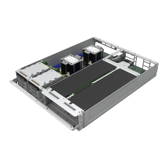
Page 101: Figure 126. 1U Liquid-Cooled Compute Module Component Identification
Intel® Server D50TNP Family Integration and Service Guide Figure 126. 1U liquid-Cooled Compute Module Component Identification Figure 127. 1U air-Cooled Compute Module Component Identification... -
Page 102: Figure 128. 2U Management Module Component Identification
Intel® Server D50TNP Family Integration and Service Guide Figure 128. 2U Management Module Component Identification Figure 129. 2U Storage Module Component Identification... -
Page 103: Server Board Features
Intel® Server D50TNP Family Integration and Service Guide Figure 130. 2U Accelerator Module Component Identification Server Board Features The following figures provide a general overview of the physical server boards, identifying key features and component locations. Figure 131. Intel® Server Board D50TNP1SB Feature Identification... -
Page 104: Figure 132. Intel® Server Board D50Tnp1Sbcr Feature Identification
Intel® Server D50TNP Family Integration and Service Guide Figure 132. Intel® Server Board D50TNP1SBCR Feature Identification The D50TNP1SB and D50TNP1SBCR server boards include several jumper blocks to configure, protect, or recover specific features of the server board. Refer to Appendix D for details. -
Page 105: Fru Replacement
This chapter provides instructions for replacement of system components considered to be field replaceable (FRU). The Intel® Server System D50TNP family features a modular design. This design allows for servicing of modules, system fans, power supply (in 2 + 1 power supply redundant configuration only), and Ethernet Management Port module (EMP module) without having to power off the entire system. -
Page 106: Module Removal / Installation
Intel® Server D50TNP Family Integration and Service Guide Module Removal / Installation Required Tools and Supplies: • Anti-static wrist strap and conductive workbench pad (recommended) 7.1.1 Module Removal 1. Power down the module using the power button on the front panel of the module to be replaced. -
Page 107: Figure 135. Installing A Module
3. Raise the lever to secure the module (see Letter B). 7.1.2.1 Storage Module Installation (D50TNP2MHSTAC Only) Important Note: When installing an Intel® Storage Module in the chassis for the very first time, the internal chassis rails need to be removed. Required Tools and Supplies: •... -
Page 108: Figure 136. Removing The Internal Chassis Rail
3. Slide the rail towards the front of the chassis to remove it (see Letter B). Do not reinstall the internal chassis rails if the chassis is used only for the Intel® Storage Module. For any other type of module installation, the internal chassis rails need to be reinstalled. Follow the instructions below to reinstall the internal chassis rails. -
Page 109: Air Duct Removal / Installation
Intel® Server D50TNP Family Integration and Service Guide Air Duct Removal / Installation To maintain system thermals, the air duct must always be in place when the system is operational. Removal of the air duct is necessary when installing or replacing any system component within the module. -
Page 110: Opening And Closing Storage Module (Ipc - D50Tnp2Mhstac)
Opening and Closing Storage Module (iPC – D50TNP2MHSTAC) The Intel® D50TNP Storage Module top tray contains the enterprise data center SSD form factor (EDSFF) units while the base of the module contains the processors, memory, and add-in cards. This section provides instructions to open and close the top tray of the storage module. -
Page 111: Closing The Top Tray
Intel® Server D50TNP Family Integration and Service Guide 7.3.2 Closing the Top Tray Figure 141. Removing the Air Duct 1. Push up the front edge of the top tray just slightly until the lock releases 2. Push the handle bar down (see Letter A) with one hand. Hold the front edge of the top tray with the other hand and lower it (see Letter B). -
Page 112: Figure 142. Processor Heat Sink Handling
Intel® Server D50TNP Family Integration and Service Guide Caution: Fin edges of the processor heat sink are very sharp. Intel recommends wearing thin ESD protective gloves when handling the PHM during the following procedures. Caution: Processor heat sinks are easily damaged if handled improperly. See the following figure for proper handling. -
Page 113: Figure 144. Reinstall The Socket Cover
Intel® Server D50TNP Family Integration and Service Guide 8. If not replacing the processor, install the original plastic socket cover over the processor socket. Figure 144. Reinstall the Socket Cover • Squeeze the finger grips at each end of the cover (see Letter A). -
Page 114: Figure 146. Processor Carrier Clip Removal From Phm Assembly
Intel® Server D50TNP Family Integration and Service Guide Figure 146. Processor Carrier Clip Removal from PHM Assembly 3. Return the lever to the original position (see Letter C). 4. Detach the processor carrier clip from the heat sink. • Unlatch the hook on each corner of the processor carrier clip and lift it from the heat sink (see Letter D). -
Page 115: Figure 148. Installing Processor Carrier Clip Onto Processor - Part 2
Intel® Server D50TNP Family Integration and Service Guide Figure 148. Installing Processor Carrier Clip onto Processor – Part 2 1. With the processor still in its tray, place the processor carrier clip over the processor. 2. Ensure the pin 1 indicator on the processor carrier clip is aligned with the pin 1 indicator of the processor. -
Page 116: Figure 150. Processor Heat Sink Anti-Tilt Wires In The Outward Position
Intel® Server D50TNP Family Integration and Service Guide Figure 150. Processor Heat Sink Anti-tilt Wires in the Outward Position 7. Set the anti-tilt wire over each of the four heat sink fasteners to their outward position. Figure 151. Pin 1 Indicator of Processor Carrier Clip 8. -
Page 117: Figure 152. Socket Protective Cover Removal
Intel® Server D50TNP Family Integration and Service Guide 7.4.1.4 PHM Installation 1. If installed, remove the plastic cover from the processor socket. Caution: Do not touch the socket pins. The pins inside the processor socket are extremely sensitive. A damaged processor socket may produce unpredictable system errors. -
Page 118: Figure 154. Phm Installation Onto Server Board
10. Reinstall the air duct and module (see Sections 7.2.2 and 7.1.2). Note: Intel strongly recommends that both processors are installed. If only one processor is installed, do not install a processor heat sink on an empty socket. -
Page 119: Processor Replacement For Evac Heat Sinks
1U standard processor heat sink (back), follow the procedures in Section 7.4.1 Caution: Fin edges of the processor heat sink are very sharp. Intel recommends wearing thin ESD protective gloves when handling the PHM during the following procedures. Caution: Processor heat sinks are easily damaged if handled improperly. See the following image for proper handling. -
Page 120: Figure 157. Removing A Riser Assembly
Intel® Server D50TNP Family Integration and Service Guide 7.4.2.1 Processor Heat Sink Module (PHM) Removal 1. Remove the riser assembly on the right side of the module. Figure 157. Removing a Riser Assembly • Remove the three screws that secure the riser assembly to the module (see Letter A). -
Page 121: Figure 159. Phm Assembly Removal From Processor Socket
Intel® Server D50TNP Family Integration and Service Guide Figure 159. PHM Assembly Removal from Processor Socket 5. Set all four anti-tilt wires on the heat sink to the inward position (see Letter D). 6. Carefully grasp the PHM and lift it straight up and off the server board (see Letter E). -
Page 122: Figure 160. Reinstall The Socket Cover
Intel® Server D50TNP Family Integration and Service Guide 9. If not replacing the processor, install the original plastic socket cover over the processor socket. Figure 160. Reinstall the Socket Cover a. Squeeze the finger grips at each end of the cover (see Letter A). -
Page 123: Figure 162. Processor Carrier Clip Removal From Phm Assembly
Intel® Server D50TNP Family Integration and Service Guide Figure 162. Processor Carrier Clip Removal from PHM Assembly 3. Return the lever to the original position (see Letter C). 4. Detach the processor carrier clip from the heat sink. a. Unlatch the hook on each corner of the processor carrier clip and lift it from the heat sink (see Letter D). -
Page 124: Figure 164. Installing Processor Carrier Clip Onto Processor - Part 2
Intel® Server D50TNP Family Integration and Service Guide Figure 164. Installing Processor Carrier Clip onto Processor – Part 2 1. With the processor still in its tray, place the processor carrier clip over the processor. 2. Ensure the pin 1 indicator on the processor carrier clip is aligned with the pin 1 indicator of the processor. -
Page 125: Figure 166. Processor Heat Sink Anti-Tilt Wires In The Outward Position
Intel® Server D50TNP Family Integration and Service Guide Figure 166. Processor Heat Sink Anti-tilt Wires in the Outward Position 7. Set the anti-tilt wire over each of the four heat sink fasteners to their outward position. Figure 167. Pin 1 Indicator of Processor Carrier Clip 8. -
Page 126: Figure 168. Socket Protective Cover Removal
Intel® Server D50TNP Family Integration and Service Guide 7.4.2.4 PHM Installation 1. If installed, remove the plastic cover from the processor socket. Caution: Do not touch the socket pins. The pins inside the processor socket are extremely sensitive. A damaged processor socket may produce unpredictable system errors. -
Page 127: Figure 170. Phm Installation Onto Server Board
Intel® Server D50TNP Family Integration and Service Guide Figure 170. PHM Installation onto Server Board 4. Set all four anti-tilt wires on the heat sink to the inward position (see Letter A). 5. Align the pin 1 indicators of the processor carrier clip and processor with the pin 1 indicator on the socket assembly bolster plate. -
Page 128: Processor Replacement For Liquid-Cooled Configurations
15. Reinstall the air duct and module (see Sections 7.2.2 and 7.1.2). Note: Intel strongly recommends that both processors are installed. If only one processor is installed, do not install a processor heat sink on an empty socket. 7.4.3 Processor Replacement for Liquid-Cooled Configurations Components Required for each faulty processor: •... -
Page 129: Figure 173. Loosening Processor Cold Plate Nuts
Intel® Server D50TNP Family Integration and Service Guide Figure 173. Loosening Processor Cold Plate Nuts 1. Fully loosen all four fasteners on the processor cold plate in any order (see Letter A). 2. Set all four anti-tilt wires on the cold plate to the inward position (see Letter B). -
Page 130: Figure 175. Reinstall The Socket Cover
Intel® Server D50TNP Family Integration and Service Guide Figure 175. Reinstall the Socket Cover 6. Reinstall the socket cover to protect the socket pins before proceeding to the next step • Squeeze the finger grips at each end of the cover and carefully lower the cover onto the socket. Then, release the finger grips. -
Page 131: Figure 177. Processor Carrier Clip Removal From Processor Cold Plate
Intel® Server D50TNP Family Integration and Service Guide Figure 177. Processor Carrier Clip Removal from Processor Cold Plate 9. Return the lever to the original position (see Letter C). 10. Detach the processor carrier clip from the processor cold plate. -
Page 132: Figure 179. Installing Processor Carrier Clip Onto Processor - Part 2
Intel® Server D50TNP Family Integration and Service Guide 12. Ensure pin 1 indicator on the processor carrier clip is aligned with pin 1 indicator of the processor. Figure 179. Installing Processor Carrier Clip onto Processor – Part 2 13. Gently press down simultaneously on two opposite sides of the processor carrier clip until it clicks in place 14. -
Page 133: Figure 181. Processor Installation Onto Server Board
Intel® Server D50TNP Family Integration and Service Guide Figure 181. Processor Installation onto Server Board Caution: Processor socket pins are delicate and bend easily. Use extreme care when placing the processor onto the processor socket. Do not drop it. 17. Align pin 1 indicators of the processor carrier clip and processor with pin 1 indicator on the bolster plate. -
Page 134: Figure 183. Applying Center Vr Thermal Gap Filler
Intel® Server D50TNP Family Integration and Service Guide Figure 183. Applying Center VR Thermal Gap Filler 19. Using the assembled applicator (see Letter A), apply the thermal gap filler on top of center processor Voltage Regulator (VR) components (see Letter B). Apply the filler only on the VR associated with the processor currently being replaced. -
Page 135: Memory (Dimm) Replacement
The figures below show standard DDR4 DIMMs but the steps of DDR4 DIMM installation and replacement are the same between standard DDR4 DIMMs and Intel® Optane™ PMem modules. Standard DDR4 DIMMs and Intel® Optane™ PMem devices will be commonly referred to as “memory device” in the following instructions. -
Page 136: Figure 186. Removing The Dimm From An Air-Cooled System
Intel® Server D50TNP Family Integration and Service Guide Figure 186. Removing the DIMM from an Air-Cooled System 1. Identify and locate the memory module to be replaced. 2. Ensure that the ejection tabs of adjacent memory slots are closed. 3. Open the ejection tabs at both ends of the selected memory slot (see Letter A). The memory module will slightly lift from the slot. -
Page 137: Ddr4 Dimm Replacement For Liquid-Cooled Modules
Intel® Server D50TNP Family Integration and Service Guide 7.5.2 DDR4 DIMM Replacement for Liquid-Cooled Modules Required Tools and Supplies: • Anti-static wrist strap and conductive workbench pad (recommended) • Phillips* head screwdriver #2 • Memory replacement tool and retention clip (see... -
Page 138: Figure 190. Removing The Dimm Retention Clips
Intel® Server D50TNP Family Integration and Service Guide Figure 190. Removing the DIMM Retention Clips 2. Identify and locate the memory module to be replaced. 3. Use the memory removal tool as a lever and position one end between the DIMM retention clip and the liquid-cooling loop (see Letter A). -
Page 139: Figure 192. Installing The Dimm In A Liquid-Cooled System
Intel® Server D50TNP Family Integration and Service Guide Figure 192. Installing the DIMM in a Liquid-Cooled System 7. Ensure that the ejection tabs at both ends of the memory slot are pushed outward to the open position (see Letter A). Use the memory replacement tool if the memory ejection tabs are in the closed position. -
Page 140: Memory Heat Spreader Thermal Pad Replacement (Liquid-Cooled Modules Only)
Note: To maintain optimal performance of the liquid-cooling loop, Intel recommends replacing ALL thermal pads at once. 1. Remove all DIMMs from the module (see Section 7.5.2). -
Page 141: Figure 195. Removing A Thermal Pad
Intel® Server D50TNP Family Integration and Service Guide Figure 195. Removing a Thermal Pad 2. Carefully peel away the thermal pads from both sides of all heat spreaders (see Letter A) and lift them up and away from the heat spreaders (see Letter B). -
Page 142: M.2 Storage Devices Replacement
Intel® Server D50TNP Family Integration and Service Guide M.2 Storage Devices Replacement This procedure applies to M.2 storage replacement for both 1U and 2U riser assemblies with illustrations showing differences where applicable. Required Tools and Supplies: • Anti-static wrist strap and conductive foam pad (recommended) •... -
Page 143: Figure 199. Installing Air-Cooled M.2 Ssd
Intel® Server D50TNP Family Integration and Service Guide If no SSD is being installed, follow steps 6 and 7. If the SSD is being replaced, skip steps 6 and 7: 6. Return the previously removed screw to the M.2 mounting standoff. -
Page 144: M.2 Ssd And Cold Plate Replacement For Liquid-Cooled Configurations
Intel® Server D50TNP Family Integration and Service Guide 7.7.2 M.2 SSD and Cold Plate Replacement for Liquid-Cooled Configurations Remove the riser assembly that the M.2 SSD is attached to (see Section 7.8). Due to the mechanical differences between the air-cooled and liquid-cooled configurations, the M.2 SSD cold plate is used to absorb the heat generated by the SSD in a liquid-cooled configuration instead of a heat sink. -
Page 145: Figure 203. Installing Liquid-Cooled M.2 Ssd
Intel® Server D50TNP Family Integration and Service Guide If no SSD is being installed, follow steps 6 and 7. If the SSD is being replaced, skip steps 6 and 7: 6. Return the previously removed screw to the M.2 mounting standoff. -
Page 146: Riser Assembly Replacement
(see Letter C). Riser Assembly Replacement The Intel® Server System D50TNP family supports either up to two (1U modules) or up to four (2U modules) low-profile PCIe* add-in cards. This section provides assembly and installation procedures for modules that require low-profile add-in card installation. -
Page 147: Figure 206. 1U Riser Assembly And Riser Card Features (D50Tnp1Mhcpac And D50Tnp2Mhstac)
Intel® Server D50TNP Family Integration and Service Guide Figure 206. 1U Riser Assembly and Riser Card Features (D50TNP1MHCPAC and D50TNP2MHSTAC) Figure 207. 1U Riser Assembly and Riser Card Features (D50TNP1MHCRAC D50TNP1MHCRLC, and D50TNP1MHEVAC) Figure 208. 2U Riser Assembly and Riser Card Features (D50TNP2MHSVAC and D50TNP2MFALAC) -
Page 148: Riser Assembly Removal
Intel® Server D50TNP Family Integration and Service Guide 7.8.1 Riser Assembly Removal 1U air-cooled module shown Figure 209. Removing a Riser Assembly 1. Remove the three screws that secure the riser assembly to the module (see Letter A). 2. Carefully remove the riser assembly by lifting it up and away from the module (see Letter B). -
Page 149: Riser Assembly Installation
Intel® Server D50TNP Family Integration and Service Guide 1U air-cooled module shown Figure 211. Add-in Card Installation 3. If installed, carefully remove the original rear metal filler plate from the metal frame of the riser assembly (see Letter A). 4. Align the rear bracket of the add-in card to the rear opening of the riser assembly. -
Page 150: Liquid-Cooling Loop Replacement (For Compute Module Ipc - D50Tnp1Mhcrlc)
Phillips* head screwdriver #2 • Torx* T-30 screwdriver • D50TNP Liquid Cooling VR TIMM Application Tools (iPC – TNPLCVRTLS) • D50TNP Liquid Cooling VR TIMM Application Nozzles (iPC – TNPLCVRTNZ) • D50TNP Liquid Cooling VR TIMM Compound (iPC – TNPLCVRCMPD) -
Page 151: Figure 214. Removing The Screws On Quick Disconnect Block And Memory Cooler
Intel® Server D50TNP Family Integration and Service Guide Figure 214. Removing the Screws on Quick Disconnect Block and Memory Cooler 1. Remove all fastener screws used to secure the quick disconnect block and memory cooler to the server board. Figure 215. Removing the Screws on the Conduction Plate... -
Page 152: Figure 216. Installing The Liquid-Cooling Loop Carrier
Intel® Server D50TNP Family Integration and Service Guide Figure 216. Installing the Liquid-Cooling Loop Carrier Note: The liquid cooling loop comes from the factory with a plastic carrier attached. The carrier is used during the installation and removal of the liquid cooling loop in the module. -
Page 153: Figure 218. Removing Liquid-Cooling Loop
Intel® Server D50TNP Family Integration and Service Guide Figure 218. Removing Liquid-Cooling Loop 7. Set all the anti-tilt wires on the cold plates to the inward position (see Letter A). 8. With your fingers, hold the liquid-cooling loop carrier (with the liquid-cooling loop attached to it) and carefully lift it up and away from the module (see Letter B). -
Page 154: Figure 220. Removing Front Vr Cooling Blocks
Intel® Server D50TNP Family Integration and Service Guide Figure 220. Removing Front VR Cooling Blocks 13. Remove the front Voltage Regulator (VR) cooling blocks. 14. Carefully unpack the new front VR cooling blocks from the liquid cooling loop replacement package. -
Page 155: Figure 221. Removing Front Vr Cooling Blocks Protective Covers
Intel® Server D50TNP Family Integration and Service Guide Note: Follow the orientation of the front VR cooling blocks as shown in the following figure during the installation on the board. Figure 221. Removing front VR Cooling Blocks Protective Covers Note: Ensure the TIM in the VR cooling blocks is not touched during subsequent installation steps. -
Page 156: Figure 223. Assembling The Manual Applicator
Intel® Server D50TNP Family Integration and Service Guide Figure 223. Assembling the Manual Applicator 17. Assemble the Bergquist SS95407 applicator, Bergquist GF3500S35 thermal gap filler cartridge, and Bergquist SS95437 nozzle as shown in the above figure. Figure 224. Applying Center VR Thermal Gap Filler 18. -
Page 157: Figure 225. Installing Liquid-Cooling Loop
Intel® Server D50TNP Family Integration and Service Guide Figure 225. Installing Liquid-Cooling Loop 22. Set all eight anti-tilt wires in the liquid cooling loop to the inward position (see Letter A). 23. With your fingers, hold the liquid-cooling loop carrier and carefully place it into the module (see Letter B). -
Page 158: Figure 227. Removing The Liquid-Cooling Loop Carrier
Intel® Server D50TNP Family Integration and Service Guide Figure 227. Removing the Liquid-Cooling Loop Carrier 26. Unscrew all 16 captive carrier screws on the plastic carrier (see Letter A) and carefully lift the carrier up and away from the module (see Letter B). -
Page 159: Mellanox Add-In Card Replacement (For Compute Module Ipc - D50Tnp1Mhcrlc)
The liquid-cooled Compute Module (D50TNP1MHCRLC) supports certain models of Mellanox add-in cards. Ensure the replacement add-in cards are compatible with liquid-cooled modules. Required Components: • New Mellanox add-in cards compatible with Intel® Server System D50TNP liquid-cooled module Required Tools and Supplies: • Anti-static wrist strap and conductive foam pad (recommended) 1. -
Page 160: Figure 230. Mellanox Liquid Cooled Add-In Card With Thermal Pad
Intel® Server D50TNP Family Integration and Service Guide Figure 230. Mellanox Liquid Cooled Add-in Card with Thermal Pad 4. Ensure the foam pads are installed on the bottom side of the add-in card. If the foam pads are not installed, the following steps can be performed in conjunction with the instruction in the add-in card documentation. -
Page 161: Accelerator Module Add-In Card Replacement (Ipc - D50Tnp2Mfalac Only)
Intel® Server D50TNP Family Integration and Service Guide 7.11 Accelerator Module Add-in Card Replacement (iPC – D50TNP2MFALAC Only) Required Tools and Supplies: • Anti-static wrist strap and conductive foam pad (recommended) • Phillips* head screwdriver #1 Figure 232. Removing a Riser Assembly 1. -
Page 162: Figure 234. Removing The Inside Screw For Oculink Cables
Intel® Server D50TNP Family Integration and Service Guide Figure 234. Removing the Inside Screw for OCuLink Cables 5. Remove the screw from the metal plate that holds two OCuLink cables along the inside of the chassis (see Letter A). 6. Carefully move the metal plate to create a slight opening to remove the two OCuLink cables (see Letter B). -
Page 163: Figure 236. Disconnecting The Riser Card Power Cables
Intel® Server D50TNP Family Integration and Service Guide Figure 236. Disconnecting the Riser Card Power Cables 8. Disconnect the riser card power cables from the connectors on the accelerator power board. Figure 237. Disconnecting Add-in Power Cable 9. Disconnect the accelerator add-in card power cables from the connectors on the power board. -
Page 164: Figure 238. Removing The Accelerator Module Riser Assembly
Intel® Server D50TNP Family Integration and Service Guide Figure 238. Removing the Accelerator Module Riser Assembly 10. Loosen the four captive screws on the Accelerator Module assembly (see Letter A). 11. Carefully remove the Accelerator Module riser assembly by lifting it up away from the module (see Letter B). -
Page 165: Figure 240. Detaching The Accelerator Add-In Card From The Riser Assembly
Intel® Server D50TNP Family Integration and Service Guide Flap not shown in figure Figure 240. Detaching the Accelerator Add-in Card from the Riser Assembly 13. Remove the two screws on each corner of the back side to detach the accelerator add-in card from the riser assembly. -
Page 166: Figure 242. Replacing The Add-In Card Metal Bracket
Intel® Server D50TNP Family Integration and Service Guide Figure 242. Replacing the Add-in Card Metal Bracket 16. Remove the screws that hold the original metal bracket on the new accelerator add-in card (see Letter A). 17. Uninstall the original metal bracket (see Letter B) from the new accelerator add-in card and replace it with the metal bracket from the existing add-in card (see Letter C). -
Page 167: Figure 244. Securing The Accelerator Add-In Card In The Riser Assembly
Intel® Server D50TNP Family Integration and Service Guide Flap not shown in figure Figure 244. Securing the Accelerator Add-in Card in the Riser Assembly 25. Fasten the two screws on each corner of the back side to firmly attach the accelerator add-in card to the riser assembly. -
Page 168: Figure 246. Connecting The Riser Card Power Cables
Intel® Server D50TNP Family Integration and Service Guide Figure 246. Connecting the Riser Card Power Cables 29. Connect the riser card power cables to the connectors on the power board. Figure 247. Connecting Add-in Card Power Cable 30. Connect the accelerator add-in card power cables to the connectors on the power board. -
Page 169: Figure 248. Installing The Oculink Cables
Intel® Server D50TNP Family Integration and Service Guide Figure 248. Installing the OCuLink Cables 31. Connect the OCuLink cables from the riser assembly to the OCuLink connectors on the server board. Note: Each OCuLink cable has the number printed on it. Connect each OCuLink cable to the OCuLink connector on the server board that has the same number. -
Page 170: Figure 250. Installing The Bracket On The Chassis
Intel® Server D50TNP Family Integration and Service Guide Figure 250. Installing the Bracket on the Chassis 34. Install the bracket to the chassis (see Letter A) and fasten the screws to secure it (see Letter B). Figure 251. Installing Riser Assembly into the Chassis 35. -
Page 171: Accelerator Module Riser Card Replacement (Ipc - D50Tnp2Mfalac Only)
Intel® Server D50TNP Family Integration and Service Guide 7.12 Accelerator Module Riser Card Replacement (iPC – D50TNP2MFALAC Only) The following provides instructions for the replacement of the riser card for the accelerator add-in card on the Intel® D50TNP Accelerator Module (D50TNP2MFALAC). -
Page 172: Figure 254. Accelerator Riser Card Installation
Intel® Server D50TNP Family Integration and Service Guide Figure 254. Accelerator Riser Card Installation 7. Locate and unpack the new accelerator riser card for replacement. 8. Slide the accelerator riser card in and align it with the screw holes on the riser assembly (see Letter A). -
Page 173: Accelerator Module Power Connector Board Replacement (Ipc - D50Tnp2Mfalac Only)
Intel® Server D50TNP Family Integration and Service Guide 7.13 Accelerator Module Power Connector Board Replacement (iPC – D50TNP2MFALAC Only) The following provides instructions for the replacement of the power connector board on the Intel® D50TNP Accelerator Module (D50TNP2MFALAC). Required Tools and Supplies: •... -
Page 174: Figure 257. Accelerator Module Power Connector Board Installation
Intel® Server D50TNP Family Integration and Service Guide Figure 257. Accelerator Module power connector board installation 5. Lower the power connector board into the slot in the module and slide it until all the screw holes are aligned (see Letter A). -
Page 175: 7.14 Intel® Virtual Raid On Cpu (Intel® Vroc) Upgrade Key Replacement
Intel® Server D50TNP Family Integration and Service Guide 7.14 Intel® Virtual RAID on CPU (Intel® VROC) Upgrade Key Replacement This section provides instructions to replace an Intel® VROC Key in the system. Refer to the Intel® Server D50TNP Family Configuration Guide for available options. -
Page 176: Figure 260. Removing The Trusted Platform Module (Tpm)
Intel® Server D50TNP Family Integration and Service Guide Figure 260. Removing the Trusted Platform Module (TPM) 4. Locate the TPM module connector on the server board. 5. Remove the fastener screw on the TPM module (see Letter A). 6. Gently remove and lift the TPM module away from the connector (see Letter B). -
Page 177: 7.16 Power Supply Replacement
Intel® Server D50TNP Family Integration and Service Guide 7.16 Power Supply Replacement Required Tools and Supplies: • Anti-static wrist strap and conductive foam pad (recommended) Figure 262. Removing the Power Supply 1. Identify the faulty power supply. 2. Detach the power cord from the power supply to be removed. -
Page 178: 7.17 Server Board Replacement
2. For air-cooled modules, remove the air duct (see Section 7.2.1). 3. Remove riser card assemblies (see Section 7.8). 4. Remove all options installed onto the server board including (if installed) the Intel® VROC 7.5 key (see Section 3.11). 5. Remove all DIMMs (see Section 7.5). -
Page 179: Figure 265. Server Board Installation
16. Reinstall DIMMs (see Section 7.5). 17. Reinstall riser card assemblies (see Section 7.8). 18. Reinstall all options previously removed from the server board, including the Intel® VROC 7.5 key (see Section 3.11). 19. For air-cooled modules, reinstall the air duct (see Section 7.2.2). -
Page 180: 7.18 System Fan Replacement
• Anti-static wrist strap and conductive foam pad (recommended) The Intel® Server System D50TNP family supports two system fan configurations as shown in the following figures – one for liquid-cooled configurations and one for air-cooled configurations. Figure 266. System Fan Configuration – Liquid-Cooled System Figure 267. -
Page 181: Figure 268. Removing The System Fan
Intel® Server D50TNP Family Integration and Service Guide Figure 268. Removing the System Fan 1. If present, remove the power supply (see Section 7.11) from the system fan assembly to be removed. 2. While pushing the green latch in the shown direction (see Letter A), use the handle to pull the system fan assembly out of the bay (see Letter B). -
Page 182: Chassis Plumbing Assembly Replacement (Liquid-Cooled Systems Only)
Intel® Server D50TNP Family Integration and Service Guide 7.19 Chassis Plumbing Assembly Replacement (Liquid-Cooled Systems Only) Select system configurations within the Intel® Server System D50TNP family support liquid-cooling on the installed modules through a passive liquid-cooling loop. The coolant flow for the liquid-cooling loop is supported through liquid-cooling plumbing connections installed in the back of the server chassis. -
Page 183: Figure 271. Removing The Quick Connect Screws
Intel® Server D50TNP Family Integration and Service Guide Figure 271. Removing the Quick Connect Screws 8. Using a Phillips head screwdriver, remove the four screws that secure each of the quick connect couplings to the covers. Figure 272. Removing Quick Connect Covers 9. -
Page 184: Figure 274. Removing The Chassis Plumbing Assembly
Intel® Server D50TNP Family Integration and Service Guide Figure 274. Removing the Chassis Plumbing Assembly 12. Using a Phillips head screwdriver, remove the six screws on the top brace of the plumbing assembly and loosen the four captive screws on the sides of the brace (see Letter A). -
Page 185: Figure 275. Installing The Chassis Plumbing Assembly
Intel® Server D50TNP Family Integration and Service Guide Figure 275. Installing the Chassis Plumbing Assembly 14. Lower the plumbing assembly inside the chassis and slide the quick connect couplings into their respective bays (see Letter A). 15. Align and secure the plumbing assembly to the chassis. Use a Phillips head screwdriver and the six screws provided on the top brace and tighten the four captive screws on the sides of the brace (see Letter B). -
Page 186: Figure 276. Installing Quick Connect Covers
Intel® Server D50TNP Family Integration and Service Guide Figure 276. Installing Quick Connect Covers 16. Install the quick connect covers by sliding them into the chassis and then pressing down. Figure 277. Securing the Quick Connect Couplings to the Covers 17. -
Page 187: Figure 278. Installing The Quick Connect Fillers
Intel® Server D50TNP Family Integration and Service Guide Figure 278. Installing the Quick Connect Fillers 18. Insert the fillers above the quick connect couplings in the back of the chassis. 19. Install the system fans (see Section 7.18). 20. Install the power supplies (see Section 7.16). -
Page 188: 7.20 Power Distribution Board (Pdb) Assembly Replacement
1. Power the system down and remove it from the rack. Important Safety Note: Due to the weight of a fully configured system, Intel recommends: - use a mechanical lift to aid with the removal of the system from the rack, and/or - use at least two people to remove the system from the rack, or - remove all installed modules from the system before attempting to remove the system from the rack. -
Page 189: Figure 281. Disconnecting The System Fan Power Cables
Intel® Server D50TNP Family Integration and Service Guide Figure 281. Disconnecting the System Fan Power Cables 5. Locate and disconnect the system fan power cables from the power distribution board by pressing inwards on each clip and lifting them up. -
Page 190: Figure 282. Removing The Power Distribution Board
Intel® Server D50TNP Family Integration and Service Guide Figure 282. Removing the Power Distribution Board 10. Remove the screws securing the power distribution board to the chassis with a Phillips head screwdriver (see Letter A). 11. Remove the PDB by lifting it upwards, tilting up the front side of the PDB, and then lifting the board out... -
Page 191: Figure 283. Installing The Power Distribution Board
Intel® Server D50TNP Family Integration and Service Guide Figure 283. Installing the Power Distribution Board 12. Remove the new PDB from its packaging. 13. Lower the PDB into the chassis, tilting down the back side and then sliding the board to the front (see Letter A). -
Page 192: Figure 284. Connecting System Fan Power Cables
Intel® Server D50TNP Family Integration and Service Guide Figure 284. Connecting System Fan Power Cables 19. Locate and connect the system fan cables by pressing inwards on each clip and pressing them down into the appropriate connector. Figure 285. Securing the Back Cover 20. -
Page 193: 7.21 Internal Chassis Rail Replacement
7.21 Internal Chassis Rail Replacement The systems within the Intel® Server System D50TNP family include internal rails to support 1U modules in the upper part of the inner walls of the chassis. Should the internal rails become damaged or worn out, this section provides the instructions necessary to replace them. -
Page 194: 7.22 System Battery Replacement
Intel® Server D50TNP Family Integration and Service Guide Figure 287. Installing the Internal Chassis Rail 7. Place the new rail inside the chassis aligning the keying pins of the rail with the chassis inner wall. 8. Slide the rail into the chassis inner wall towards the back of the chassis until it locks into place. -
Page 195: Figure 289. Installing The System Battery
Intel® Server D50TNP Family Integration and Service Guide Figure 289. Installing the System Battery 7. Insert the battery into the battery socket (see above figure). 8. Reinstall the riser assemblies (see Section 7.7). 9. Reinstall the module in the chassis (see Section 7.1.2). -
Page 196: Appendix A. Getting Help
Intel Configure to Order tool. If a solution cannot be found at Intel’s support site, submit a service request via Intel’s online service center at https://supporttickets.intel.com/servicecenter?lang=en-US . In addition, you can also view previous support requests. (Login required to access previous support requests) Contact an Intel support representative using one of the support phone numbers available at https://www.intel.com/content/www/us/en/support/contact-support.html... -
Page 197: Appendix B. Memory Population Rules
• Only Intel® Optane™ PMem modules are supported. • In an Intel server system, support for Intel® Optane™ persistent memory 200 series module is only available on air-cooled systems. • Intel® Optane™ persistent memory 200 series modules are only supported in DIMM slot 2 (black slot) and the slot 1 (blue slot) in the same memory channel must be populated with one DDR4 DIMM. -
Page 198: Table 4. Intel® Optane™ Persistent Memory 200 Series Module Support
Intel® Server D50TNP Family Integration and Service Guide • Intel® Optane™ persistent memory 200 series modules must be populated symmetrically for each installed processor (corresponding slots populated on either side of each processor) and across both processors. Table 4. Intel® Optane™ Persistent Memory 200 Series Module Support Intel®... -
Page 199: Appendix C. System Status Led State Definitions
IPMI “Chassis Identify” command that causes the LED to blink for 15 seconds. • NMI Button – When the NMI button is pressed, it puts the Intel® D50TNP Module in a halt state and issues a non-maskable interrupt (NMI). This can be useful when performing diagnostics for a given issue where a memory download is necessary to help determine the cause of the problem. -
Page 200: Table 7. Intel® D50Tnp Module Status Led State Definitions
Intel® Server D50TNP Family Integration and Service Guide Table 7. Intel® D50TNP Module Status LED State Definitions LED State Module State BIOS Status Description • System power is not present. No AC Power to system • Module is in EuP Lot6 off mode. - Page 201 Intel® Server D50TNP Family Integration and Service Guide LED State Module State BIOS Status Description • CPU CATERR signal asserted. • MSID mismatch detected (CATERR also asserts for this case). • CPU 0 is missing. • CPU Thermal Trip. • No power good – power fault.
-
Page 202: Appendix D. Onboard Configuration And Service Jumpers
Intel® Server D50TNP Family Integration and Service Guide Appendix D. Onboard Configuration and Service Jumpers The Intel® Server Boards D50TNP1SB and D50TNP1SBCR includes several jumper blocks to configure, protect, or recover specific features of the server board. The following figure identifies the location of each jumper block on the server board. -
Page 203: Bios Default Jumper (Bios Dflt - J17)
Note: The module automatically powers on if AC power is connected to the server chassis. 8. Power on the Intel® D50TNP Module and press <F2> during POST to access the BIOS Setup utility to configure and save desired BIOS options. -
Page 204: Intel® Management Engine (Intel® Me) Firmware Force Update Jumper (Me_Frc_Updt - J13)
(ME_FRC_UPDT – J13) When the Intel® ME firmware force update jumper is moved from its default position, the Intel® ME is forced to operate in a reduced minimal operating capacity. This jumper should only be used if the Intel® ME firmware has gotten corrupted and requires reinstallation. -
Page 205: Bmc Force Update Jumper (Bmc_Frc_Updt - J2X4)
BMC to abort its normal boot process and stay in the boot loader without executing any Linux* code. This jumper should only be used if the BMC firmware has become corrupted and requires reinstallation. Note: The BMC firmware update files are included in the SUP posted to Intel’s download center. See Table 1. -
Page 206: Bmc Svn Downgrade (J33)
Caution: When downgrading to an older version of BMC, modules may end up with a firmware stack combination that is not supported, and therefore could experience unpredictable behavior. Note: Latest system update packages are included in the SUP posted to Intel’s download center. See Table 1. -
Page 207: Appendix E. Post Code Diagnostic Led Decoder
Intel® Server D50TNP Family Integration and Service Guide Appendix E. POST Code Diagnostic LED Decoder As an aid in troubleshooting a system hang that occurs during a system POST process, the server board includes a bank of eight POST code diagnostic LEDs on the back edge of the server board. -
Page 208: Early Post Memory Initialization Mrc Diagnostic Codes
Intel® Server D50TNP Family Integration and Service Guide Early POST Memory Initialization MRC Diagnostic Codes Memory initialization at the beginning of POST includes multiple functions: discovery, channel training, validation that the DIMM population is acceptable and functional, initialization of the IMC and other hardware settings, and initialization of applicable RAS configurations. -
Page 209: Table 10. Mrc Fatal Error Codes
Intel® Server D50TNP Family Integration and Service Guide Note: Fatal MRC errors display POST error codes that may be the same as BIOS POST progress codes displayed later in the POST process. The fatal MRC codes can be distinguished from the BIOS POST progress... -
Page 210: Bios Post Progress Codes
Intel® Server D50TNP Family Integration and Service Guide BIOS POST Progress Codes The following table provides a list of all POST progress codes. Table 11. POST Progress Codes Post Upper Nibble Lower Nibble Code Description (Hex) SEC Phase First POST code after CPU reset... - Page 211 Intel® Server D50TNP Family Integration and Service Guide Post Upper Nibble Lower Nibble Code Description (Hex) MRC Progress Codes – At this point the MRC Progress Code sequence is executed. Memory Installed CPU PEIM (CPU Init) CPU PEIM (Cache Init)
- Page 212 Intel® Server D50TNP Family Integration and Service Guide Post Upper Nibble Lower Nibble Code Description (Hex) DXE PCI Bus HPC Init DXE PCI Bus enumeration DXE PCI Bus resource requested DXE PCI Bus assign resource DXE CON_OUT connect DXE CON_IN connect...
-
Page 213: Appendix F. Post Error Codes
Pause” option setting in the BIOS Setup does not have any effect on this error. Note: The POST error codes in the following table are common to all current generation Intel® server platforms. Features present on a given server board/system determine which of the listed error codes are... -
Page 214: Table 12. Post Error Messages And Handling
Intel® Server D50TNP Family Integration and Service Guide Table 12. POST Error Messages and Handling Error Code Error Message Action message Type 0012 System RTC date/time not set Major 0048 Password check failed Put right password. Major 0140 PCI component encountered a PERR error... - Page 215 Intel® Server D50TNP Family Integration and Service Guide Error Code Error Message Action message Type 8523 Memory failed test/initialization CPU0_DIMM_B1 Remove the disabled DIMM. Major 8524 Memory failed test/initialization CPU0_DIMM_B2 Remove the disabled DIMM. Major 8525 Memory failed test/initialization CPU0_DIMM_B3 Remove the disabled DIMM.
- Page 216 Intel® Server D50TNP Family Integration and Service Guide Error Code Error Message Action message Type 8551 Memory disabled.CPU0_DIMM_F3 Remove the disabled DIMM. Major 8552 Memory disabled.CPU0_DIMM_G1 Remove the disabled DIMM. Major 8553 Memory disabled.CPU0_DIMM_G2 Remove the disabled DIMM. Major 8554 Memory disabled.CPU0_DIMM_G3...
- Page 217 Intel® Server D50TNP Family Integration and Service Guide Error Code Error Message Action message Type Memory encountered a Serial Presence Detection(SPD) Major 8571 failure.CPU0_DIMM_F3 Memory encountered a Serial Presence Detection(SPD) Major 8572 failure.CPU0_DIMM_G1 Memory encountered a Serial Presence Detection(SPD) Major 8573 failure.CPU0_DIMM_G2...
- Page 218 Intel® Server D50TNP Family Integration and Service Guide Error Code Error Message Action message Type 85D4 Memory disabled.CPU1_DIMM_E1 Remove the disabled DIMM. Major 85D5 Memory disabled.CPU1_DIMM_E2 Remove the disabled DIMM. Major 85D6 Memory disabled.CPU1_DIMM_E3 Remove the disabled DIMM. Major 85D7 Memory disabled.CPU1_DIMM_F1...
-
Page 219: Processor Initialization Error Summary
Processor Initialization Error Summary Table 13 describes mixed processor conditions and actions for all Intel server boards and Intel server systems designed with the Intel® Xeon® Scalable processor family architecture. The errors fall into one of the following categories: •... -
Page 220: Table 13. Mixed Processor Configurations Error Summary
Displays 0197: Processor speeds unable to synchronize message in the error manager. • Takes fatal error action (see above) and does not boot until the fault condition is remedied If the link frequencies for all Intel® Ultra Path Interconnect (Intel® UPI) links can be adjusted to be the same: •... -
Page 221: Appendix G. Product Safety - Multi-Language
Intel® Server D50TNP Family Integration and Service Guide Appendix G. Product Safety – Multi-Language WARNING: English (US) The power supply in this product contains no user-serviceable parts. There may be more than one supply in this product. Refer servicing only to qualified personnel. - Page 222 Intel® Server D50TNP Family Integration and Service Guide For proper cooling and airflow, always reinstall the chassis covers before turning on the system. Operating the system without the covers in place can damage system parts. To install the covers: 1. Check first to make sure you have not left loose tools or parts inside the system.
- Page 223 Intel® Server D50TNP Family Integration and Service Guide AVERTISSEMENT: Français Le bloc d'alimentation de ce produit ne contient aucune pièce pouvant être réparée par l'utilisateur. Ce produit peut contenir plus d'un bloc d'alimentation. Veuillez contacter un technicien qualifié en cas de problème.
- Page 224 Intel® Server D50TNP Family Integration and Service Guide Afin de permettre le refroidissement et l’aération du système, réinstallez toujours les panneaux du boîtier avant de mettre le système sous tension. Le fonctionnement du système en l’absence des panneaux risque d’endommager ses pièces. Pour installer les panneaux, procédez comme suit:...
- Page 225 Intel® Server D50TNP Family Integration and Service Guide WARNUNG: Deutsch Benutzer können am Netzgerät dieses Produkts keine Reparaturen vornehmen. Das Produkt enthält möglicherweise mehrere Netzgeräte. Wartungsarbeiten müssen von qualifizierten Technikern ausgeführt werden. Versuchen Sie nicht, das mitgelieferte Netzkabel zu ändern oder zu verwenden, wenn es sich nicht genau um den erforderlichen Typ handelt.
- Page 226 Intel® Server D50TNP Family Integration and Service Guide Zur ordnungsgemäßen Kühlung und Lüftung muß die Gehäuseabdeckung immer wieder vor dem Einschalten installiert werden. Ein Betrieb des Systems ohne angebrachte Abdeckung kann Ihrem System oder Teile darin beschädigen. Um die Abdeckung wieder anzubringen: 1.
- Page 227 Intel® Server D50TNP Family Integration and Service Guide AVVERTENZA: Italiano Rivolgersi ad un tecnico specializzato per la riparazione dei componenti dell'alimentazione di questo prodotto. È possibile che il prodotto disponga di più fonti di alimentazione. Non modificare o utilizzare il cavo di alimentazione in c.a. fornito dal produttore, se non corrisponde esattamente al tipo richiesto.
- Page 228 Intel® Server D50TNP Family Integration and Service Guide Per il giusto flusso dell’aria e raffreddamento del sistema, rimettere sempre le coperture del telaio prima di riaccendere il sistema. Operare il sistema senza le coperture al loro proprio posto potrebbe danneggiare i componenti del sistema. Per rimettere le coperture del telaio: 1.
- Page 229 Intel® Server D50TNP Family Integration and Service Guide ADVERTENCIAS: Español El usuario debe abstenerse de manipular los componentes de la fuente de alimentación de este producto, cuya reparación debe dejarse exclusivamente en manos de personal técnico especializado. Puede que este producto disponga de más de una fuente de alimentación.
- Page 230 Intel® Server D50TNP Family Integration and Service Guide Para obtener un enfriamiento y un flujo de aire adecuados, reinstale siempre las tapas del chasis antes de poner en marcha el sistema. Si pone en funcionamiento el sistema sin las tapas bien colocadas puede dañar los componentes del sistema. Para instalar las tapas: 1.
- Page 231 Intel® Server D50TNP Family Integration and Service Guide אזהרה: עברית אספקת חשמל אספקת החשמל במוצר זה לא מכילה חלקים שניתנים לשירות על ידי משתמש. ייתכן שיש יותר ממקור .אחד במוצר זה. לקבלת שירות יש לפנות רק אל אנשים המוסמכים לכך...
- Page 232 Intel® Server D50TNP Family Integration and Service Guide את מכסי המעטפת לפני הפעלת המערכת. הפעלת המערכת ללא לקירור ולזרימת אוויר תקינים, יש תמיד להתקין מחדש :המכסים במקומם, עלולה לגרום נזק לחלקי המערכת. להתקנת המכסים .יש לבדוק תחילה כדי לוודא שלא נשארו כלים או חלקים רופפים בתוך המערכת...
-
Page 233: Appendix H. Glossary
Intel® Server D50TNP Family Integration and Service Guide Appendix H. Glossary Term Definition One rack unit (1.75 in.) Two rack units (3.5 in.) BIOS Basic input output system; non-volatile firmware Baseboard management controller Coolant Distribution Unit Chassis Casing containing the server modules and fans/liquid cooling plumbing...
Need help?
Do you have a question about the D50TNP and is the answer not in the manual?
Questions and answers