Table of Contents
Advertisement
Quick Links
Advertisement
Table of Contents

Related Manuals for Rinnai Brivis DONSC10Z71


Summary of Contents for Rinnai Brivis DONSC10Z71
- Page 1 Brivis ICE Inverter INSTALLATION INSTRUCTIONS OUTDOOR INDOOR Brivis System Models Outdoor Indoor DONSC10Z71 DINLU10Z7 DONSC13Z71 DINLU13Z7 DONSC15Z71 DINLU15Z7 DONSC17Z71 DINXU17Z7 PLEASE READ THESE INSTRUCTIONS CAREFULLY BEFORE INSTALLING & USING THIS PRODUCT...
-
Page 2: Table Of Contents
Table of Contents 1.0 INTRODUCTION ............................. 3 1.1 Brivis ICE R410a Inverter Range ......................3 1.2 Safety / Warnings ............................ 3 1.3 Codes / Regulations ..........................3 2.0 COMPONENTS ............................4 2.1 Indoor Unit (Cooling Coil) ........................4 2.2 Starting Collars ............................5 2.3 P-Trap .............................. -
Page 3: Introduction
INSTALLATION, START-UP & MAINTENANCE INSTRUCTIONS 1.0 INTRODUCTION Read all instructions before proceeding with the installation and start up. • This equipment must be installed in accordance with all relevant regulatory authority and industry requirements. Only qualified, licensed technicians shall perform works on these units; failure to do so will result in warranty being •... -
Page 4: Codes / Regulations
1.3 Codes / Regulations Brivis ICE units must be installed, serviced or repaired in accordance with these instructions and related regulations, codes, standards, and authorities. These include but may not be limited to: • Ozone Protection and Synthetic Greenhouse Gas Management Regulations 1995 AS/ NZS 1677.2 - Australian Standard, Refrigeration systems, safety requirements for fixed applications •... -
Page 5: Starting Collars
Fig. 1b – DINLU Indoor Cooling Coil Power Cord & Plug Electric P-Trap Assembly Access Plate 2.2 Starting Collars Insert starting collar (pop) into the hole in pop plate, ensuring pop flange is placed over the inner supply air wall of the cabinet. -
Page 6: P-Trap
Fig. 2b – DINLU Indoor Unit Starting Collar Assembly Rivets (Supplied) flange 2.3 P-Trap The Indoor Unit incorporates an evaporator drip tray and is supplied with a 20mm Female Pressure Pipe drain spigot, which is to be connected to the "P" trap. Always install the “P”... -
Page 7: Outdoor Unit
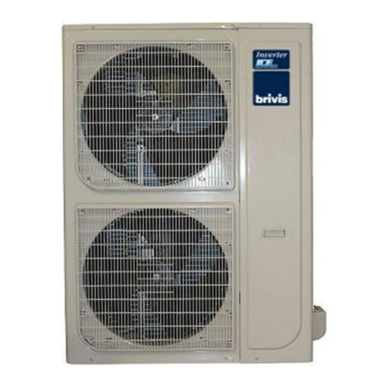
2.4 Outdoor Unit Fig. 5 - Outdoor Units DONSC10Z71 DONSC13Z71, 15Z71 & 17Z71... -
Page 8: Typical Installation
3.0 TYPICAL INSTALLATION Fig. 6 - Typical Indoor Unit Installation Ensure 1m minimum, or preferably 2½ times the duct diameter, STRAIGHT duct length before any take-offs occur Ensure 1m minimum STRAIGHT duct between the Gas Ducted Heater and ICE coil unit Safety Drain Tray (field supplied), independently drained Working Platform (field supplied) -
Page 9: Indoor Unit Installation
4.0 INDOOR UNIT INSTALLATION Indoor coils are supplied with a nitrogen holding charge ranging from 400kPa to 700kPa • • Connect a suitable pressure gauge to the indoor coil valve to ensure the internal pressure is at least 400kPa • If the measured pressure is less than 400kPa, check and if necessary repair any leaks found before proceeding Remove the nitrogen holding charge by connecting a charging line with valve depressor •... -
Page 10: Location
4.1 Location Choose a location that is suitable for refrigeration piping and condensate drainage • Allow adequate provision is made for service access • • Indoor Coil Unit is not weatherproof and should be installed so that there is no chance of direct sunlight, water or moisture coming into contact with the outer casing Where the unit is installed in the roof or ceiling space ensure the building structure is capable of supporting the unit’s •... -
Page 11: Electrical Connection
4.4 Electrical Connection The electric box has standard 3 m, 10 A power cord and plug; do not cut or modify the cord • 24 Volt control wiring shall be installed from the indoor coil electric box (Terminals A1, A2) to the Heater (StarPro •... -
Page 12: General Arrangement Drawings
4.8 General Arrangement Drawings Fig. 9 - Indoor Unit Dimensions – Model DINXU17Z7 Fig. 10 - Indoor Unit Dimensions Models - DINLU10Z7, DINLU13Z7 & DINLU15Z7... -
Page 13: Outdoor Unit Installation
5.0 OUTDOOR UNIT INSTALLATION 5.1 Location • The unit must be installed in accordance with relevant authority requirements. The unit should not be accessible to general public • • Do not install the unit where there is a possibility it will present a noise problem for either the home owner or neighbours, or exceed the noise guidelines as set down by local or state legislation or regulatory bodies. -
Page 14: Wiring Diagrams
5.4 Wiring Diagrams Fig. 11 – Typical Indoor Unit Wiring Diagram (DINXU & DINLU SERIES) - Page 15 Fig. 12 – Wiring Circuit for Brivis StarPro Series Heaters with Brivis ICE Add-On Using Brivis Networker NG-2A Electronic Control Module ZONE / TSTAT ZONE B ZONE A G W R ADD-ON TW1 TW2 INDOOR UNIT ELECTRIC BOX Brivis Networker StarPro model heaters can be configured for zoning and/or Add-On Refrigerative Air Conditioning.
- Page 16 Fig. 14 – Shielded Communication Cable Between Indoor and Outdoor Units...
-
Page 17: General Arrangement Drawings & Clearance Requirements Outdoor Unit
5.5 Dimensional Drawings & Clearance Requirements Outdoor Unit Fig. 15 – Outdoor Unit Dimensions MODEL Size DONSC10Z71 1030 DONSC13Z71 DONSC15Z71 13 / 15 / 17 1333 1045 DONSC17Z71 Table 2 – Brivis ICE Inverter Outdoor Unit Dimensions... -
Page 18: Refrigeration Charge & Pipe-Work
Fig. 16 – Outdoor Unit Clearances 6.0 REFRIGERATION CHARGE & PIPE-WORK WARNING: • Both indoor and outdoor units come delivered under positive pressure • The Outdoor Unit is charged with sufficient R410a refrigerant for an interconnecting pipe run of 15m actual length The indoor unit is pressurised with 400kPa to 700kPa dry nitrogen •... -
Page 19: Piping Design
6.1 Piping Design Pipe-work shall be installed in a manner which prevents drainage of liquid into the compressor and ensures • adequate oil return • During operation, temperature of gas pipe and liquid pipe shall be over-heating or over-cooling extremely. Therefore, it is necessary to carry out insulation;... -
Page 20: Pipe-Work Connection
6.2 Pipe-work connection Sweat connection: • Locate the suction & liquid pipe service valves in the compressor compartment by removing the service access panel Check that the service valves are tightly closed (Service Ball valves have been provided for suction and liquid •... -
Page 21: Expelling The Air With The Vacuum Pump
• Be sure to use both a spanner and torque wrench together when connecting/disconnecting pipe to/from the unit. NOTE: Too large torque will harm the bell-mouthing and too small will cause leakage. Please determine the torque according to the table below. Leak test the unit after finishing the connection. Tightening Torque N M (Turn clockwise to close) Stop Shaft (valve body) -
Page 22: Charging The System
Fig. 18 – Vacuum Pump Application 6.4 Charging the system Once all electrical connections are correctly made, the unit is ready to be commissioned. Refrigerant may only be added after performing a leak test and system evacuation Start the system in cool mode and allow it to stabilise before checking liquid line sub-cooling and compressor suction superheat. -
Page 23: Start-Up And Commissioning
7.0 Start-Up and Commissioning Ensure that a Return Air Filter is fitted prior to fan start up • Measure and record the system details as noted under PRELIMINARY SYSTEM INFORMATION and check all • items as noted under PRE START-UP on the Commissioning Sheet provided •... -
Page 24: Sequence Of Operation
7.1 Sequence of Operation Check correct sequence of operation, then proceed to instruct customer on correct thermostat operation for refrigerated cooling. Refer to the thermostat operating instructions. Ventilation Set the thermostat to the fan only mode. The fan only will start and operate continuously. Cooling On a call for cooling the compressor and outdoor fan/s will start and cycle in response to the thermostat to maintain the desired room temperature. -
Page 25: Cooling Capacity
7.2 Cooling Capacity DONSC10Z71 / DINLU10Z7 (678 L/s) Air Temperature Return Air Temperature Entering Outdoor Dry Bulb°C Wet Bulb°C Dry Bulb°C Wet Bulb°C Dry Bulb°C Wet Bulb°C Unit °C 10.34 11.04 TC KW 10.84 7.83 8.21 9.60 SC KW TC KW SC KW TC KW SC KW... -
Page 26: Specifications
7.3 Specifications Brivis ICE Inverter - Technical Specifications System Overview Nominal Capacity Power Supply V-Ph-Hz 220~240-1-50 Rated Capacity 10.01 13.07 14.57 16.24 Capacity Range 4.8 ~ 11.0 6.3 ~ 14.0 7.5 ~ 16.0 8.3 ~ 16.6 Cooling Rated Input Power 3.20 4.08 4.67... -
Page 27: Commissioning Sheet
7.4 Commissioning Sheet Installer; please complete all sections of this form. SYSTEM INFORMATION ICE MODEL SERIAL No. (Outdoor Unit) (Outdoor Unit) ICE MODEL SERIAL No. (Indoor Unit) (Indoor Unit) HEATER MODEL HEATER SERIAL No. INSTALLED BY/ DATE PRE START-UP (Please tick boxes below as each item is completed). VERIFY THAT ALL PACKAGING MATERIALS HAVE BEEN REMOVED FROM UNIT.
Need help?
Do you have a question about the Brivis DONSC10Z71 and is the answer not in the manual?
Questions and answers